
Ultimate DIY LiFePO4 Battery Build Guide: 12V, 24V and 48V
Build a 12.8V, 25.6V or 51.2V LiFePO4 battery with EVE MB31 314Ah cells
This guide shows how to choose the right pack voltage, match the BMS, inspect and restrain the cells, verify every connection and commission the finished battery without using the BMS as the normal operating control.
Sixteen EVE MB31 cells make a 51.2V, 314Ah battery storing just over 16kWh. Eight make an 8kWh 24V-class pack, while four make a 4kWh 12V-class pack. The cells are the same, but the current, BMS, copper, protection and sensible inverter size are very different.
Read this before touching a busbar
A large LiFePO4 pack can deliver destructive fault current even when its nominal voltage is below 60V. Cell terminals remain live. A BMS, open switch or removed fuse does not make the cell string electrically dead.
This article is educational and does not replace the EVE, JK, inverter, fuse, enclosure or installation instructions. In Queensland, the Electrical Safety Office says a licensed electrician should install a battery energy storage system, including a custom-made battery bank. Fixed wiring, inverter connection, grid connection, switchboard work and final BESS commissioning belong with appropriately licensed people. A DIY battery may also be unsuitable for a grid-connected installation, approved-product requirement, rebate, warranty or insurer.
What this guide covers
- Choosing 12V, 24V or 48V
- Why use EVE MB31 cells?
- Choosing the correct JK BMS
- Parts and tools
- Incoming cell inspection
- Top-balancing decisions
- Mechanical assembly
- BMS sense-lead verification
- Fuse, isolation and pre-charge
- Conservative JK settings
- Deye, Victron and Growatt
- First power-up and commissioning
- Parallel battery packs
- Maintenance and documentation
1. Choose voltage from current, not habit
The correct place to start is the largest continuous inverter load, expected surge, lowest normal battery voltage, inverter efficiency and allowable voltage drop. Do not start with “I have always used 12V.”
The approximate battery current is:
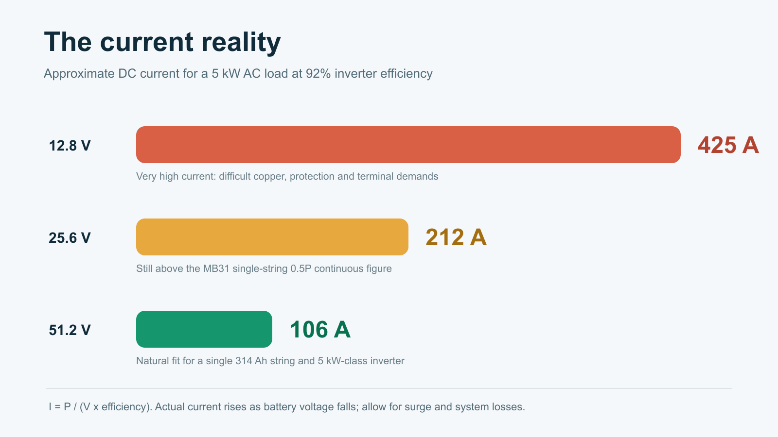
At 92% inverter efficiency, a 5kW load requires approximately 425A from a 12.8V pack, 212A from a 25.6V pack and 106A from a 51.2V pack. Actual current rises as battery voltage falls, and surge, inverter self-consumption and conductor losses add more.
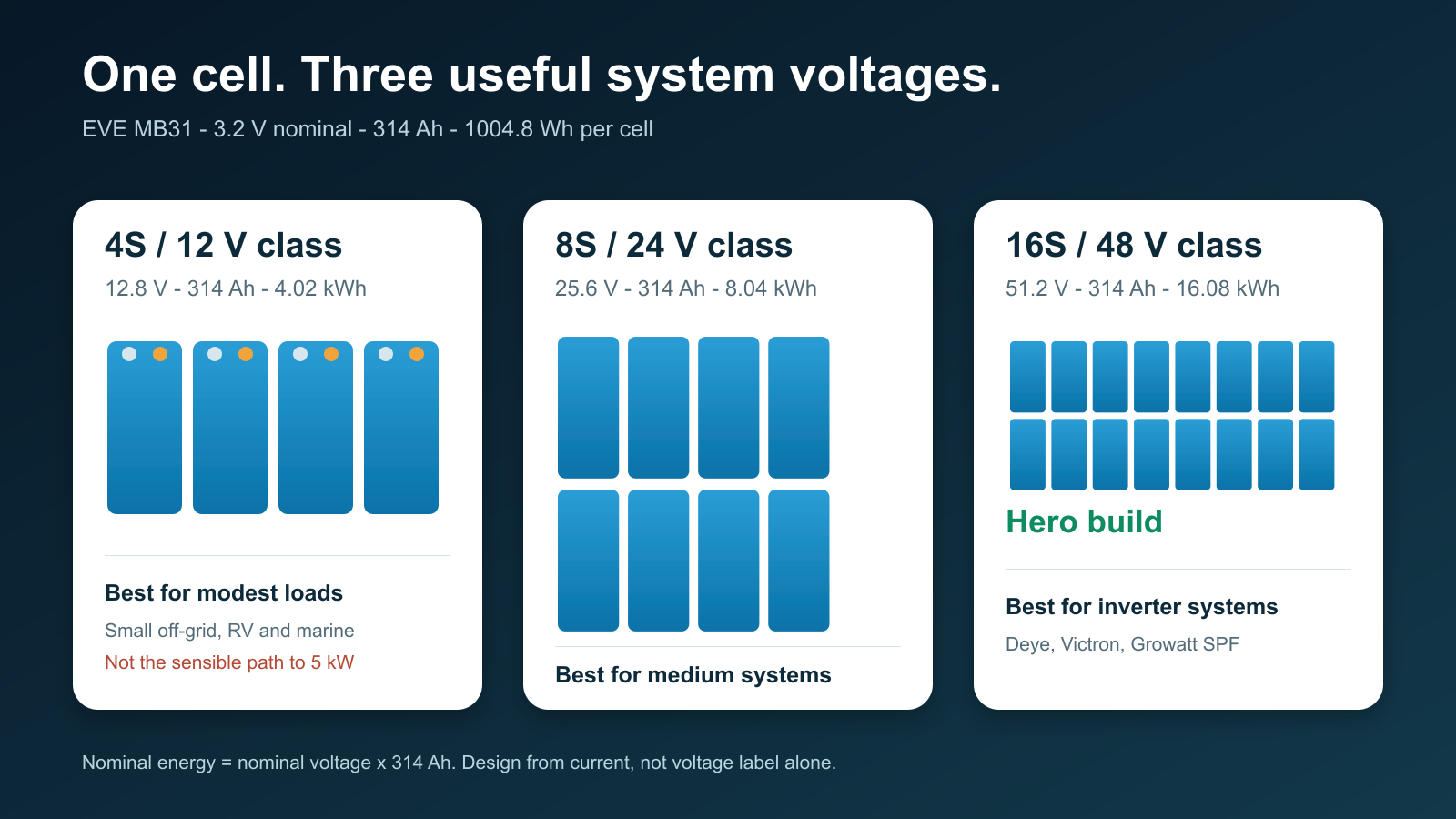
12.8V / 4.02kWh
Best for modest RV, marine and small off-grid loads. A single MB31 string is not a sensible route to a continuous 3-5kW inverter.
25.6V / 8.04kWh
A practical middle ground for medium off-grid systems and roughly 2-3kW inverter loads when the complete current design supports it.
51.2V / 16.08kWh
The hero build for home storage and modern inverter systems. It naturally suits a 5kW-class Deye, Victron or Growatt installation.
2. Why the EVE MB31 314Ah?
The MB31 is a strong all-round energy-storage cell. EVE lists 314Ah nominal capacity, 3.2V nominal voltage, 1004.8Wh nominal energy, approximately 5.6kg weight and 0.5P/0.5P standard charge/discharge capability.
Its greatest DIY advantage is not only capacity. The 280-314Ah prismatic-cell format has a mature ecosystem of enclosures, busbars, insulation, restraint systems and BMS hardware. That makes a 16-cell, 16kWh pack easier to support than many newer oversized cell formats.
For a broader comparison, read our EVE MB31 vs LF334 vs REPT 345Ah decision guide.
3. Match the BMS to the actual pack
The BMS must match the chemistry, series count, normal current, surge behaviour, temperature requirements and inverter communication method.
| Pack | JK selection | Important limitation |
|---|---|---|
| 4S / 12.8V | A genuine 4S-capable JK model | The reviewed JK PB1/PB2 16S family does not cover 4S. See our JK 4-8S first-start guide. |
| 8S / 25.6V | A correctly rated 8S JK, or a compatible PB model after firmware/protocol verification | The reviewed PB manual covers 7-16S electrically, but inverter communication at 24V still needs confirmation for the exact hardware. |
| 16S / 51.2V | JK PB inverter BMS matched to the required current | Confirm hardware revision, firmware, CAN/RS485 protocol and pinout for the actual inverter. |
Never choose a BMS only because its headline current rating matches the inverter. A 200A BMS can still be the wrong choice if the cell, terminal, conductor, busbar, enclosure or fuse cannot safely support the intended current.
4. Parts and tools
Cells, BMS and monitoring
- 4, 8 or 16 traceable EVE MB31 314Ah cells
- JK BMS matched to the exact series count, current and communication requirement
- All specified cell and BMS/MOS temperature sensors
- Compatible JK display/interface board where required
- Verified CAN or RS485 cable built from the exact two product pinouts
Mechanical assembly and insulation
- Rigid enclosure with service access and protected conductor entries
- Engineered restraint with flat end plates
- Cell-to-cell insulation and a non-conductive base
- Terminal and busbar covers
- Strain relief, abrasion protection and secure BMS mounting
The reviewed EVE specification lists a recommended cell compression force of 3000-7000N and an instantaneous maximum of 10000N. This is force across the cell face, not threaded-rod torque. Do not invent a bolt torque without an engineered clamp geometry and measurement method.
Power path and tools
- Busbars and terminal hardware suited to the actual cell variant
- DC-rated fuse with suitable voltage rating, interrupt rating and time-current behaviour
- Load-rated DC disconnect where required by the design
- Conductors, lugs and supports sized for the installation method
- Pre-charge resistor and switching method designed for the inverter input capacitance
- CAT-rated multimeter, insulated probes and insulated tools
- Calibrated torque wrench or screwdriver
- Proper lug crimper and cable cutter
- Thermal camera for staged-load commissioning
EVE specifies a maximum pole torque of 6N·m in the reviewed MB31 datasheet. Confirm that value against the actual terminal variant, adapters and fasteners supplied. Use a calibrated tool and record the final result.
5. Inspect the cells before assembly
Do not assemble first and discover a problem later. Record the supplier, batch/QR information, physical condition, resting voltage and consistently measured internal resistance for every cell. Capacity-test if that is part of the acceptance plan.
Quarantine any cell with a dent, swelling, leak, corroded or damaged terminal, abnormal voltage or unexplained measurement outlier. A severely over-discharged cell should not be “recovered” as part of a public tutorial.
6. Top balancing: choose a controlled method
Top balancing is a commissioning process, not a ritual that must be repeated routinely. Two defensible approaches are common:
- Parallel top balance before assembly: bring the cells to the same upper state of charge with a current-limited bench supply, verified polarity, temperature monitoring and continuous supervision.
- Assemble and commission slowly: construct the series pack, verify every sense connection, charge at low controlled current and allow the active balancer to correct the upper-curve spread.
Do not use a “set the supply and walk away” method. The process needs current limiting, supervision, a clear termination criterion and respect for EVE’s 3.65V absolute charge limit. For a dedicated walkthrough, see How to Top Balance LiFePO4.
7. Mechanical assembly
- Prepare a clean, dry, non-conductive bench and remove jewellery.
- Confirm cell orientation against a printed series map.
- Install cell-to-cell insulation before fitting busbars.
- Place cells into the restraint system without lifting from the terminals.
- Apply controlled, even restraint within the manufacturer’s force limits.
- Install one busbar at a time while neighbouring terminals stay covered.
- Use only an approved method to prepare mating surfaces.
- Tighten with the correct sequence and calibrated torque tool.
- Apply a torque mark and replace the terminal cover immediately.
- Compare measured total series voltage with the sum of the individual cells.
Never rest the BMS, tools, fasteners or loose busbars on exposed cells.
8. Verify every BMS sense lead before connection
A misplaced balance lead can damage the BMS or create a short through the harness. Wire colour alone is not proof.
- Leave the BMS sense connector unplugged.
- Attach the harness to the cell string in the exact order shown in the manual.
- Measure each adjacent step at the unplugged connector: B0-B1, B1-B2 and onward should each show one cell voltage with correct polarity.
- Measure cumulatively from B0 to every successive pin. Voltage should rise by one cell at each step.
- Stop if any step is negative, zero or close to two cell voltages.
- Verify B-, P-, display, communication and temperature connections.
- Only insert the sense connector after an independent recheck.
9. The BMS is not the fuse
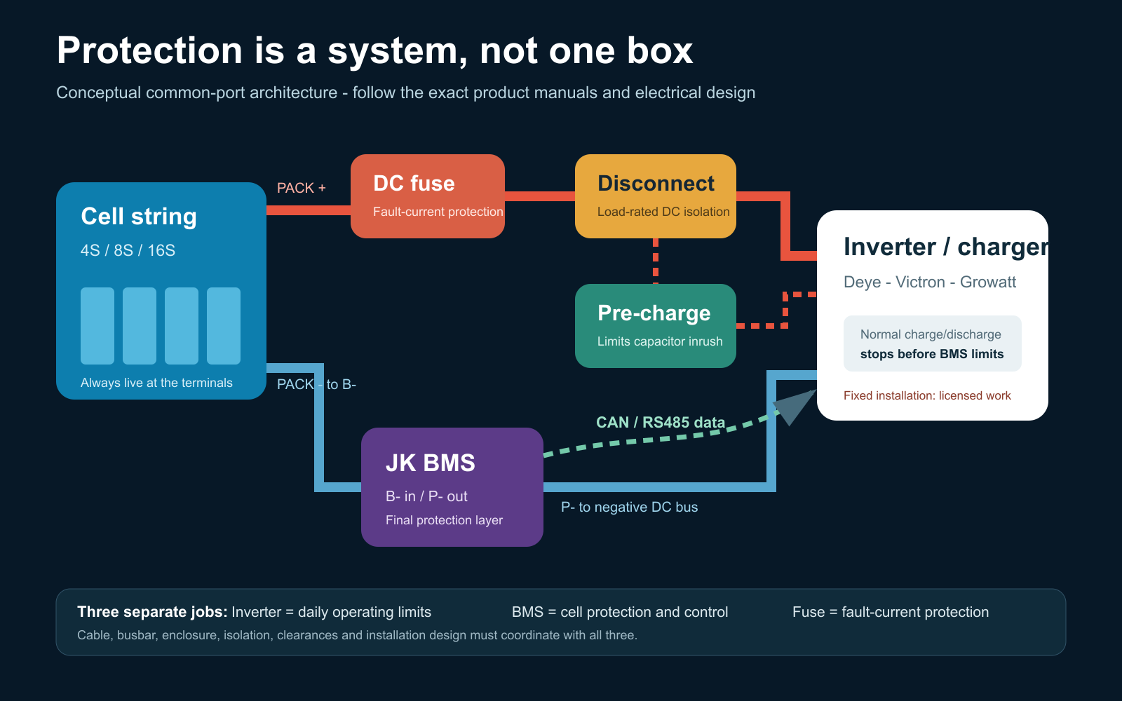
In a common-port MOSFET arrangement, cell-string negative connects to BMS B-, and BMS P- connects to the negative DC bus. Cell-string positive goes through the engineered positive protection and isolation path to the DC bus. Follow the exact JK manual for the hardware being used.
The fuse protects against fault current. It requires an adequate DC voltage rating, interrupt capacity and time-current relationship with the conductors and equipment. A pre-charge circuit limits inverter-capacitor inrush before the main path is closed. Read our discussion of 48V battery circuit breakers and Class T fuses.
An RJ45 connector does not guarantee an Ethernet pinout. Verify both ends of every JK-to-inverter communication cable and continuity-test it before connection.
10. Conservative JK settings for an MB31 pack
The best settings make the inverter stop normal operation first, keep the BMS as the last-resort guardrail and leave the fuse to clear serious fault current.
| Function | Starting value | Purpose |
|---|---|---|
| Chemistry | LiFePO4 | Select before entering other values. |
| Cell count | 4, 8 or 16 as physically built | Verify from the harness and cumulative voltage. |
| Capacity | 314Ah or measured usable capacity | Establishes the coulomb-counter baseline. |
| Balance start | About 3.40V/cell | Balances on the upper curve rather than chasing mid-curve load sag. |
| Balance delta | 10-15mV | Avoids hunting over tiny dynamic differences. |
| Controlled charge ceiling | 3.55V/cell | Leaves margin below EVE’s 3.65V maximum. |
| Cell OVP | About 3.60V | Last-resort high-cell protection. |
| OVP recovery | About 3.45V | Provides useful hysteresis. |
| SOC 100% | 3.50V/cell | Synchronises the fuel gauge; it is not the charge cutoff. |
| Float / maintenance | 3.40V/cell if required | Avoids holding the pack at its charge ceiling. |
| Cell UVP | 2.80V/cell | Hard BMS cutoff. Do not design routine cycling to 2.5V. |
| UVP recovery | About 3.00-3.05V/cell | Coordinate with restart behaviour. |
| Charge low-temperature stop | 0°C | Matches the lower end of EVE’s listed charge range. |
| Charge low-temperature recovery | 3-5°C | Prevents cycling at freezing point. |
| Emergency mode | OFF | It overrides normal protections and is not an operating mode. |
Pack-voltage equivalents
| Pack | Charge at 3.55V/cell | 100% sync at 3.50V/cell | Float at 3.40V/cell | BMS UVP at 2.80V/cell |
|---|---|---|---|---|
| 4S | 14.2V | 14.0V | 13.6V | 11.2V |
| 8S | 28.4V | 28.0V | 27.2V | 22.4V |
| 16S | 56.8V | 56.0V | 54.4V | 44.8V |
Do not simply enter the BMS’s maximum current as the charge/discharge limit. The operational current must respect the MB31 continuous limit, conductor and busbar ampacity, terminal temperature, fuse coordination and inverter behaviour. Over-current delays, short-circuit delay and smart-sleep behaviour must be verified against the exact JK firmware.
LiFePO4 does not need lead-acid-style float charging. If an inverter requires a float field, 3.40V/cell is a conservative maintenance value for this project. See our separate LiFePO4 float-voltage guide.
11. Deye, Victron and Growatt SPF integration
Closed-loop CAN or RS485 communication can allow the BMS to report SOC, alarms, requested charge voltage, charge-current limit and discharge-current limit. It does not remove the need for safe fallback settings.
Deye / SunSynk
- Record the full JK and Deye model, hardware revision and firmware.
- Verify CAN versus RS485 and both connector pinouts.
- Select the matching JK inverter protocol and lithium/BMS mode.
- Confirm SOC, requested voltage, current limits and alarms on both devices.
- Disconnect communication in a controlled test and prove the intended fallback/fault response.
Victron
A Victron system may use a GX device, DVCC and compatible CAN-bus integration, or it may run open-loop. Do not assume native support until the exact JK firmware/protocol and Victron architecture have been tested. Existing site references include connecting a JK inverter BMS to Victron and the Victron Multi RS 48/6000 JK CAN example.
Growatt SPF
Growatt SPF is a family, not one universal protocol. Confirm the full inverter model and firmware, CAN/RS485 requirement, battery protocol, pinout, lithium-menu selection and safe open-loop fallback values.
12. First power-up and commissioning
Before energising
- Cell model, quantity and polarity match the drawing.
- No damaged or quarantined cell is installed.
- Restraint and insulation are complete.
- Every busbar and terminal is torqued, marked and covered.
- Every adjacent and cumulative sense voltage is correct.
- B-/P-, fuse, disconnect, conductor and pre-charge designs have been checked.
- Temperature probes are installed at representative locations.
- The inverter is isolated from AC, grid and PV as required by its shutdown procedure.
Controlled commissioning sequence
- Wake the BMS without the inverter load and compare every cell reading with the multimeter.
- Check all temperature sensors and alarm states.
- Verify charge/discharge switching and the configured limits.
- Pre-charge the inverter using the designed method.
- Close the main DC path only after the voltage difference has fallen to the design criterion.
- Begin at low power and compare BMS, external meter and inverter readings.
- Increase load in planned steps while recording cell delta, voltage drop and temperatures.
- Thermally inspect terminals, busbars, BMS and conductors after a meaningful load soak.
Stop for a hot connection, rising cell temperature, swelling, abnormal smell or sound, unstable voltage, unexplained cell divergence or a mismatch between instruments. Do not deliberately short the pack or force cells beyond safe limits to “test” protections for a video.
13. Parallel packs need separate protection
Parallel packs are separate energy sources. Each pack needs a compatible BMS and normally its own branch fuse and isolation, connected to an engineered common bus.
- Match chemistry, series count and operating voltage.
- Bring pack voltages close before connection.
- Use an engineered current-sharing/busbar arrangement.
- Configure unique BMS addresses where required.
- Confirm how total charge and discharge limits reach the inverter.
- Prove that one isolated pack cannot overload the remaining pack.
Never connect packs at significantly different voltages and expect the BMS to control equalisation current.
14. A good battery finishes with documentation
A battery is not finished merely because it turns on. Keep a permanent pack record containing:
- one-line diagram and cell-series map
- cell and BMS datasheets
- final settings and firmware versions
- cell inspection, torque and thermal-test records
- fuse, disconnect, conductor and pre-charge details
- shutdown, restart and emergency procedures
- SDS location, maintenance schedule and alarm meanings
Future checks should review enclosure condition, moisture or pests, event logs, cell-delta trends, terminal condition and temperature under a known load. Do not casually retorque live terminals.
The build philosophy in one minute
- Choose voltage from current and inverter power.
- Keep normal continuous current within the cell and complete-system limits.
- Inspect and document every cell before assembly.
- Restrain, insulate, torque and cover the pack correctly.
- Verify every balance lead with a meter before connecting the BMS.
- Make the inverter stop normal operation before the BMS guardrails.
- Use 3.55V/cell charge, 3.50V/cell SOC sync, 3.40V/cell float if required and 2.80V/cell only as the hard low-voltage cutoff.
- Commission in controlled stages and record the thermal result.
Technical references
- EVE MB31 product information
- JK official support and PB specifications
- Queensland Electrical Safety Office BESS guidance
- Clean Energy Council approved batteries and product-safety transition
- 2026 AS/NZS 5139 amendment summary
For the Australian installation boundary, also read Safe Installation of LiFePO4 Batteries in Australia.