News Lithium Battery-school
Used LiFePO4 Cells Sold as New: The 2026 Second-Life Battery Problem

Q. Is the B-grade and used-cell problem still real in 2026?
A. YES. The risk is lower than it was a few years ago, but the problem has not disappeared. It has changed.

New LiFePO4 cell prices have fallen. Manufacturing quality has improved. Large manufacturers are producing more cells, better traceability is coming, and genuine new cells are easier to buy than they once were.

At the same time, the first enormous wave of electric vehicles, buses, trucks and commercial battery packs is getting older. Packs only a few years old are being damaged, written off, dismantled, tested and split into modules and individual cells. Some of those cells are perfectly suitable for an honest second-life application.

But some are being cleaned, rewrapped, relabelled and sold into another supply chain without the buyer being told that they are used.

SECOND-LIFE CELLS ARE NOT THE PROBLEM.

SELLING SECOND-LIFE CELLS AS NEW IS THE PROBLEM.

This article is not an attack on battery recycling. Proper reuse is good engineering and good environmental practice. It is also not a claim that every low-cost battery contains used cells. The point is simple: buyers must be told what they are buying, and claims such as new, Grade A, matched and automotive grade must be supported by real evidence.

What Has Changed Since the Original QR-Code Problem?

In the earlier article, The LiFePO4 QR Code B-to-A-Grade Problem, I explained why a QR code does not authenticate a cell. A QR code is data. It can be copied, printed, engraved or replaced.

In 2026 the bigger question is no longer only, “Was this B-grade cell made to look like A-grade?”

The new question is: “Was this cell already inside another battery?”

The International Energy Agency’s 2026 battery analysis says flows of used and end-of-life EV batteries are beginning to increase and used-battery prices have fallen sharply. The same report says China hosts more than 85% of global battery-recycling capacity. That does not mean 85% of used cells are being misrepresented. It means an enormous dismantling, reuse and recycling industry now exists around these batteries.

China introduced stronger rules from 1 April 2026, including a digital identity for EV power batteries and a national traceability system. The Chinese Government said the volume of retired batteries is growing significantly. A national lifecycle traceability platform now aims to follow batteries from production and installation through use, retirement and recycling.

Governments do not build national tracking systems for an imaginary product flow.

First, Stop Mixing Up Four Different Things

TermWhat it should meanWhat the buyer must be told
New cellUnused cell supplied through a traceable manufacturing and distribution chain.Manufacturer, model, production batch, test data and warranty source.
B-grade or factory-second cellA new cell that did not meet one or more first-grade production or matching criteria.That it is B grade, why it was rejected if known, and what testing has been completed.
Second-life or repurposed cellA cell that has already been used in a vehicle, module or another battery and is being used again.Its previous use, test method, measured state of health, limitations and second-life warranty.
Recycled materialLithium, copper, aluminium or other materials recovered and processed for manufacturing again.This is material recovery—not the same thing as selling an intact used cell.

A used cell can be better than a poor new cell. A properly tested automotive cell at 85% state of health may be excellent for a low-rate, stationary project. But it is still used. Its value, warranty, expected life and suitable application are different.

What I Have Personally Seen

I have watched hundreds and probably thousands of videos on Chinese social-media platforms showing businesses that specialise in this work.

  • Complete EV and commercial battery packs arriving on pallets.
  • Packs opened and modules separated.
  • Cells removed, cleaned and tested.
  • Old insulation, films, busbars and labels removed.
  • New wraps, terminal covers and labels fitted.
  • Cells sorted into different piles according to voltage, capacity or what the workshop believes it can sell them for.
  • Modules and cells advertised into completely different markets.

Recycling and repurposing businesses are not hiding the fact that they do this work. Many are proud of it. It is a large and legitimate industry when the product remains identified as used or repurposed.

The issue is what happens further down the sales chain. A video cannot prove where every cell eventually goes, and I will not pretend that it can. But once a cell has been cleaned, wrapped and separated from its original BMS data and pack identity, the next buyer may have no simple way to know its history.

A 2026 report based on a Yicai investigation described an unlicensed workshop where retired packs were dismantled, cells were tested and higher-capacity cells were re-filmed for resale into two-wheelers, power banks and energy-storage products. Read the reported investigation into China’s informal battery-recycling market. Caixin separately reported in June 2026 that less than 30% of retired power batteries were being collected through formal channels. These are reported estimates, not a measurement of every battery or seller.

Why a Used Cell Can Look Brand New

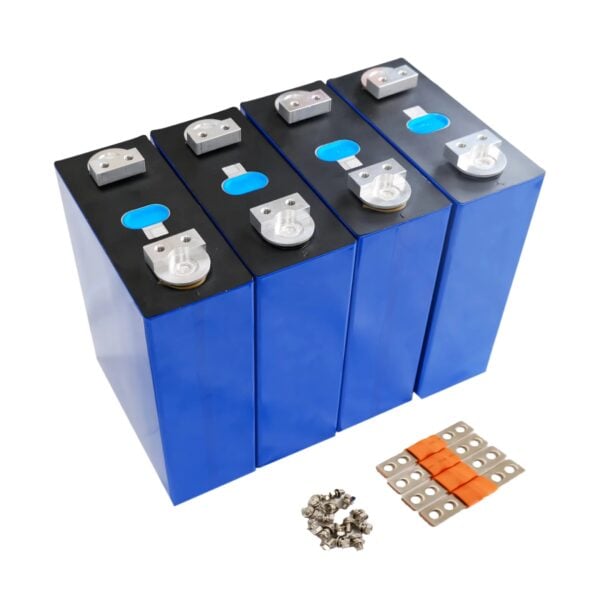
A prismatic cell is an aluminium can with terminals, a vent, a plastic top and a thin outer film. Most of what a buyer sees can be cleaned or replaced.

  1. The old pack is tested as a complete unit.
  2. The pack is dismantled into modules or cells.
  3. Obvious failures are separated from cells that still hold useful capacity.
  4. Residue, adhesive and old film are removed.
  5. Terminals can be cleaned or resurfaced and new covers fitted.
  6. A new wrap, label or QR mark gives the cell a uniform appearance.
  7. The cells are boxed with new busbars and sold into another market.

None of this changes what is inside the can. It does not put the lithium back. It does not undo heat exposure. It does not remove calendar ageing, high-current use, deep discharge, overcharge, vibration, compression damage or years of self-discharge history.

A NEW WRAP IS NOT A NEW CELL.

A NEW QR CODE IS NOT A NEW CELL.

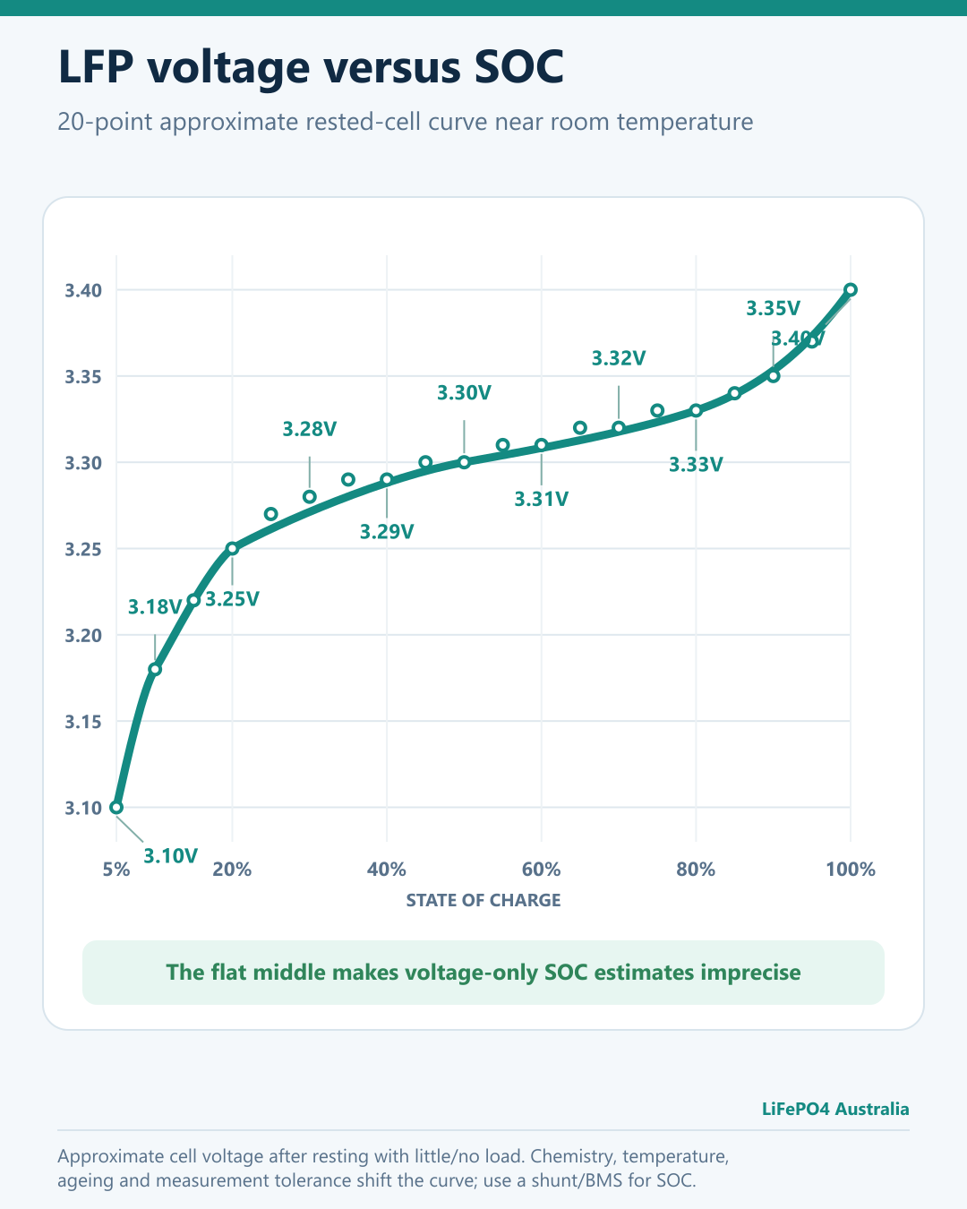
A VOLTAGE OF 3.29V IS NOT A STATE-OF-HEALTH TEST.

Why the QR Code Still Does Not Save You

A QR code may tell you what the code claims the cell is. It may include a manufacturer identifier, model and production date. That can be useful for detecting an obvious mismatch.

It cannot tell you:

  • whether the mark is original;
  • whether the cell spent three years inside a bus or commercial battery;
  • how many amp-hours it can deliver now;
  • its self-discharge rate;
  • its DC internal resistance at a controlled state of charge and temperature;
  • whether it was exposed to excessive heat or damaging voltage limits; or
  • whether sixteen cells came from the same original batch, or even the same pack.

If you want the background, read our LiFePO4 QR vendor-code guide and the original explanation of why QR codes do not verify authenticity.

The Technical Problem Is Cell History and Cell Mismatch

Second-life engineering is not just “charge it and see if it reaches 3.65V.”

A peer-reviewed study of cells harvested from a retired LiFePO4 hybrid-vehicle pack found high state-of-health variation and mismatch within modules. Depending on the acceptance criteria, the proportion considered suitable for reuse changed significantly. That is the entire problem in one result: the answer depends on what was measured and what standard was applied.

Another second-life assessment of commercial LFP batteries retired from EVs evaluated capacity, impedance, balance state and consistency. Research using 920 retired-LFP datasets was needed to develop a faster method of estimating residual capacity. If a simple voltage check or QR scan were enough, this research would not be necessary.

UL’s standard for repurposing batteries makes the same point in practical language. UL 1974 covers examination, BMS-data analysis, disassembly, sorting, grading, rejection procedures, markings and instructions. Proper repurposing is a process, not a sticker.

One Weak Cell Still Controls the Whole Series Pack

Let us use a current 16-cell, 51.2V battery example.

  • 15 cells can deliver 314Ah.
  • One used or damaged cell can deliver only 240Ah.
  • The cells are in series.

Theoretical nominal energy with properly matched 314Ah cells:

16 × 3.2V × 314Ah = 16.08kWh

Energy limited by the 240Ah cell:

16 × 3.2V × 240Ah = 12.29kWh

That single weak cell can remove about 23.6% of the usable capacity before allowing for inverter losses, BMS limits and reserve settings. It may also reach the charge or discharge limit first, causing the BMS to disconnect the entire battery.

This is why a pack can appear normal at rest, charge to the expected voltage, and still perform badly under load.

Is a Properly Disclosed Second-Life Battery Bad?

NO.

A proper second-life battery may offer excellent value. Retired EV batteries can retain substantial usable capacity. The IEA, NREL, CATL, UL and many researchers are all investigating or supporting reuse because the idea is technically valid.

A legitimate second-life product should be sold as second-life.

It should have traceable origin, a defined screening and rejection process, measured state-of-health data, an application-appropriate design, a realistic warranty and a clear future recycling pathway.

CATL says traceability makes second life and recycling more viable, and describes battery passports as a way to retain lifecycle identity. Its formal battery-health service uses extensive online and offline inspections. See CATL’s circularity and traceability overview and its battery inspection and lifecycle service.

The honest second-life seller is not the enemy here. In many cases that seller is doing more testing and providing more information than a seller hiding behind the words “A Grade.”

How to Reduce the Risk Before You Buy

1. Ask who supplied the cells

“Direct from the factory” is not a document. Ask for the legal supplier name, invoice trail, manufacturer batch information and who will honour the warranty in Australia.

2. Ask whether the cells have ever been installed

Do not ask only whether they are “new.” Ask whether they have ever been installed in a pack, vehicle, test system, demonstration unit or another product.

3. Ask for the original factory data—not a seller spreadsheet

A spreadsheet can be copied just like a QR code. The value comes from a traceable connection between the manufacturer, the batch, the individual cells and the business accepting responsibility for the claim.

4. Demand test conditions

  • Capacity in amp-hours and watt-hours.
  • Charge and discharge current.
  • Upper and lower voltage limits.
  • Cell temperature during testing.
  • DC internal resistance measured at the same state of charge and temperature.
  • Self-discharge observation period.
  • Acceptance and rejection limits.

5. Look for physical evidence

  • Uneven or freshly replaced wraps.
  • Adhesive residue or marks where old separators were attached.
  • Scratched terminals or signs of previous busbar contact.
  • Sanded, polished or resurfaced terminal faces.
  • Inconsistent vents, terminal covers, heights, weights or case finish.
  • QR codes with different depth, alignment, font or surface finish.
  • Swelling, dents, corrosion or electrolyte residue.

Physical clues can raise questions, but they are not a complete state-of-health test. A carefully refurbished cell may look perfect, and a genuine new cell can have minor cosmetic marks.

6. Compare the price with reality

New-cell prices have fallen, so a low price is not automatic proof of fraud. But a claimed premium, fully matched, automotive-grade product still needs a supply chain and testing process capable of producing that result. If the price cannot pay for the product, dangerous-goods transport, GST, testing, warranty and local support, ask which part is missing.

7. Buy from someone who will still answer the phone

The most useful certificate is worthless if nobody accepts responsibility when one cell develops high self-discharge six months later.

For more background on how we describe cell quality, see our separate LiFePO4 battery-grades guide and the earlier report on B-grade EVE QR markings.

What Australian Sellers and Buyers Should Know

The ACCC says claims about a product’s quality, history and whether it is new must be accurate and based on reasonable grounds. It also says silence can be misleading when important information is withheld. Read the ACCC’s guidance on false or misleading claims.

This is not theoretical. The ACCC previously took action involving electronics advertised as new when they were refurbished or made with used parts. See the ACCC’s refurbished-electronics enforcement example.

Battery safety is also more than chemistry. The ACCC’s lithium-ion battery safety guide tells consumers to buy from reputable suppliers and not use dented, swollen, leaking, overheated or damaged batteries. Australia’s battery-reuse industry is legitimate and growing, but used batteries need proper systems. The 2026 ABRI and Standards Australia transport guidance exists because used lithium batteries require specific handling, packaging, labelling and risk controls.

This article provides general information, not legal advice. The principle is still plain enough: if a product is used, say it is used.

The Bottom Line

The risk of receiving old stock or obvious factory rejects may be lower than it was several years ago because genuine new LFP cells are cheaper and easier to source.

But another supply is growing at the same time: cells recovered from EVs, buses, commercial storage systems, damaged packs, insurance write-offs and early battery projects.

Many of those cells still have useful life. They should be tested, graded, matched and sold honestly for an appropriate application.

USED IS NOT A DIRTY WORD.
UNDISCLOSED IS THE DIRTY WORD.

Do not pay new-cell money for an unknown history. Do not accept a QR scan as proof. Ask for evidence, test data, traceability and somebody in Australia who will stand behind the product.

Sources and Further Reading

How these sources are ranked: official and peer-reviewed sources support factual and technical claims. Investigations describe current market behaviour. Forum posts are individual reports and discussions; they are useful for recognising patterns but are not treated as independently verified proof against a seller.

Tier 1 — Official, primary and standards sources

  1. IEA — Global EV Outlook 2026: Electric vehicle batteries
  2. IEA — Battery Circularity (2026)
  3. Government of China — management of used NEV power batteries
  4. China MIIT — power-battery recycling and utilisation measures
  5. China SASAC — national battery traceability platform
  6. UL Solutions — UL 1974 and repurposed batteries
  7. CATL — battery recycling and closed-loop utilisation
  8. CATL — traceability, battery passports and circularity
  9. CATL — formal battery-health assessment and lifecycle service
  10. ACCC — false or misleading claims
  11. ACCC Product Safety — selling second-hand products
  12. ACCC Product Safety — lithium-ion battery guide
  13. CSIRO/ACCC — Lithium-ion battery safety report
  14. ABRI — Used Lithium Batteries safety guidance (2026)

Tier 2 — Peer-reviewed and institutional research

  1. Statistical state-of-health assessment of LFP cells from a retired vehicle pack
  2. Second-Life Assessment of Commercial LiFePO4 Batteries Retired from EVs
  3. State-of-health estimation of second-life LiFePO4 batteries
  4. Rapid residual-capacity estimation using 920 retired-LFP datasets
  5. NREL — A Second Life for Electric Vehicle Batteries
  6. Health diagnosis and recuperation of aged lithium-ion batteries
  7. UTS — state-of-health estimation for second-life batteries
  8. Formal and informal EV-battery recycling channels (2026)

Tier 3 — Current reporting and investigations

  1. Caixin — China’s retired-battery wave and illegal recycling crackdown
  2. CarNewsChina/Yicai — reported investigation of an unlicensed dismantling workshop
  3. Caixin — safety and testing concerns for retired batteries in energy storage
  4. SCMP — China’s retired-battery circular economy

Tier 4 — Specialist testing and buyer resources

  1. EVreporter — spotting counterfeit LFP cells
  2. Akkudoktor — documented inspection of B-grade cells
  3. Tüftler und Heimwerker — tested cells carrying a B mark
  4. Power Forum — high-current automotive-grade cell comparison
  5. Wistek — decoding EVE QR serial numbers

Tier 5 — Community reports and discussion

  1. DIY Solar Power Forum — Second Life Lithium Batteries
  2. DIY Solar Power Forum — buyer discussion involving claimed re-lasered cells
  3. DIY Solar Power Forum — second-life CALB cells reportedly represented as new
  4. DIY Solar Power Forum — battery disassembly and capacity report
  5. DIY Solar Power Forum — cells advertised as new/original that did not test accordingly
  6. DIY Solar Power Forum — recovery of cells from an older EV pack
  7. Reddit SolarDIY — listing changed from new to refurbished after purchase
  8. Reddit SolarDIY — openly sold used CATL battery pack discussion
  9. Reddit SolarDIY — buyer discussion about Grade A and Grade B cells

Published in 2026. This article distinguishes verified technical information, reported market estimates and the author’s own observations. External forum links are supplied for further reading and do not constitute an endorsement of every statement made by their users.

Blog Lithium Battery-school News
Why the Deye RW-F16 Is Not Suitable for Most Australian Homes

The Deye RW-F16 is a 51.2V, 16kWh lithium iron phosphate battery. On paper, its capacity and price may look attractive. But a battery is not suitable for an Australian home simply because it uses LiFePO4 cells or has a circuit breaker and battery-management system.

As at 17 August 2026, the RW-F16 does not appear on the official Clean Energy Council approved-battery list. Deye’s own product page lists its certifications as UN38.3, CE and CB—not Australian approval or certification to SA TS 5398.

UN38.3 is primarily a transport-safety standard, while CE marking relates to the European market. Neither replaces the product assessment and installation requirements applicable in Australia.

View Deye’s RW-F16 specifications or check the official CEC approved-battery data.

For the overwhelming majority of Australian homeowners, that makes the RW-F16 an unsuitable choice at present.

Why the approved-battery list matters

To qualify for Australia’s Cheaper Home Batteries Program, a battery must be on the CEC approved-battery list, comply with AS/NZS 5139 and applicable state or territory electrical-safety laws, and be installed by an appropriately accredited installer.

An unlisted battery will not qualify for the federal incentive and may also be rejected by installers, networks, government programs or other parties that require approved equipment. The Clean Energy Regulator publishes the current solar-battery eligibility requirements.

Certifications are not just paperwork

Standards such as IEC 62619 and UL 1973 examine important aspects of stationary-battery safety, including abnormal operating conditions, protection systems and the battery’s response to foreseeable faults.

They should not, however, be treated as interchangeable badges or described as a universal requirement that every Australian battery must hold simultaneously. The important question is whether the exact model has independently verified evidence of compliance through an accepted Australian pathway and is listed for its intended application.

It is also more accurate to talk about a CEC approved-product listing than a generic “CEC certificate”. The listing relates to the exact model and its supporting compliance evidence.

SA TS 5398 is changing the Australian market

Australia is now transitioning to SA TS 5398: Electrical Energy Storage Equipment – Safety Requirements.

  • New applications can presently be assessed under SA TS 5398 or the transitional Best Practice Guide.
  • From 1 January 2027, new applications will only be accepted with SA TS 5398 certification.
  • Remaining listings approved under the old guide will expire no later than 31 December 2027.

Other regulators, networks and programs may adopt SA TS 5398 sooner. The Clean Energy Council’s transition timetable should be checked before a battery is purchased or specified.

The electrical and fire risks are real

Every battery carries risk. Every electrical system carries risk. That is precisely why Australia licenses electrical workers and requires electrical equipment and installations to meet minimum standards.

A 51.2V, 314Ah battery can deliver an enormous amount of fault current. Poorly selected cables, loose connections, unsuitable terminals, inadequate fault-current protection or incorrectly coordinated fuses and circuit breakers can produce extreme heat, arcing, fire or explosion.

A battery-management system is not a substitute for correctly engineered cables, isolation, overcurrent protection and installation practices.

This is not an allegation that every unlisted battery will catch fire, nor that this particular Deye model is inherently defective. It means Australian consumers presently lack the complete, locally recognised approval pathway that should be expected before placing a 16kWh energy-storage device in or beside a home.

Queensland’s Electrical Safety Office warns that incorrect battery installation can cause electric shock, fire, flash burns, explosion and exposure to hazardous chemicals. It also notes that arc-flash temperatures can exceed 12,000°C. See its battery energy storage system safety guidance.

Fire and insurance exposure

A non-compliant product or installation can also create serious insurance complications. It does not automatically void every policy, because coverage depends on the policy wording and the cause of a loss.

However, after a fire, an insurer may investigate whether the equipment was approved, whether the electrical work was lawful, whether relevant standards and manufacturer instructions were followed, and whether required information was disclosed.

That is not a position a homeowner wants to argue after a catastrophic fire.

What Australian buyers should do

The sensible approach is straightforward: choose the exact battery model from the current CEC approved list, confirm the evidence supporting its listing and future SA TS 5398 status, and have the complete system designed and installed by properly licensed and accredited professionals.

Until the Deye RW-F16 obtains the necessary recognised approvals and appears on the Australian approved-product list, it is not a responsible recommendation for most Australian households.

A lower purchase price is not a saving if it comes at the expense of eligibility, insurability, compliance or safety.

This article provides general information, not electrical, legal or insurance advice. Requirements and approved-product listings can change. Check the current rules and consult appropriately licensed professionals before buying or installing a battery system.

Blog Lithium Battery-school
Ultimate DIY LiFePO4 Battery Build Guide: 12V, 24V and 48V
The complete planning, assembly and commissioning guide

Build a 12.8V, 25.6V or 51.2V LiFePO4 battery with EVE MB31 314Ah cells

This guide shows how to choose the right pack voltage, match the BMS, inspect and restrain the cells, verify every connection and commission the finished battery without using the BMS as the normal operating control.

View EVE MB31 cells
View the JK DIY cabinet

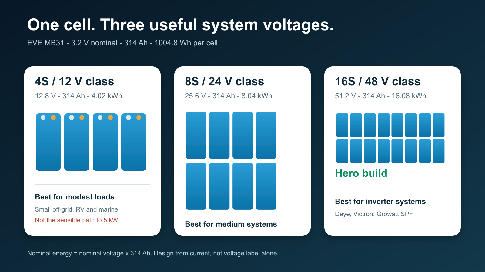
Sixteen EVE MB31 cells make a 51.2V, 314Ah battery storing just over 16kWh. Eight make an 8kWh 24V-class pack, while four make a 4kWh 12V-class pack. The cells are the same, but the current, BMS, copper, protection and sensible inverter size are very different.

Read this before touching a busbar

A large LiFePO4 pack can deliver destructive fault current even when its nominal voltage is below 60V. Cell terminals remain live. A BMS, open switch or removed fuse does not make the cell string electrically dead.

This article is educational and does not replace the EVE, JK, inverter, fuse, enclosure or installation instructions. In Queensland, the Electrical Safety Office says a licensed electrician should install a battery energy storage system, including a custom-made battery bank. Fixed wiring, inverter connection, grid connection, switchboard work and final BESS commissioning belong with appropriately licensed people. A DIY battery may also be unsuitable for a grid-connected installation, approved-product requirement, rebate, warranty or insurer.

What this guide covers

  1. Choosing 12V, 24V or 48V
  2. Why use EVE MB31 cells?
  3. Choosing the correct JK BMS
  4. Parts and tools
  5. Incoming cell inspection
  6. Top-balancing decisions
  7. Mechanical assembly
  8. BMS sense-lead verification
  9. Fuse, isolation and pre-charge
  10. Conservative JK settings
  11. Deye, Victron and Growatt
  12. First power-up and commissioning
  13. Parallel battery packs
  14. Maintenance and documentation

1. Choose voltage from current, not habit

The correct place to start is the largest continuous inverter load, expected surge, lowest normal battery voltage, inverter efficiency and allowable voltage drop. Do not start with “I have always used 12V.”

The approximate battery current is:

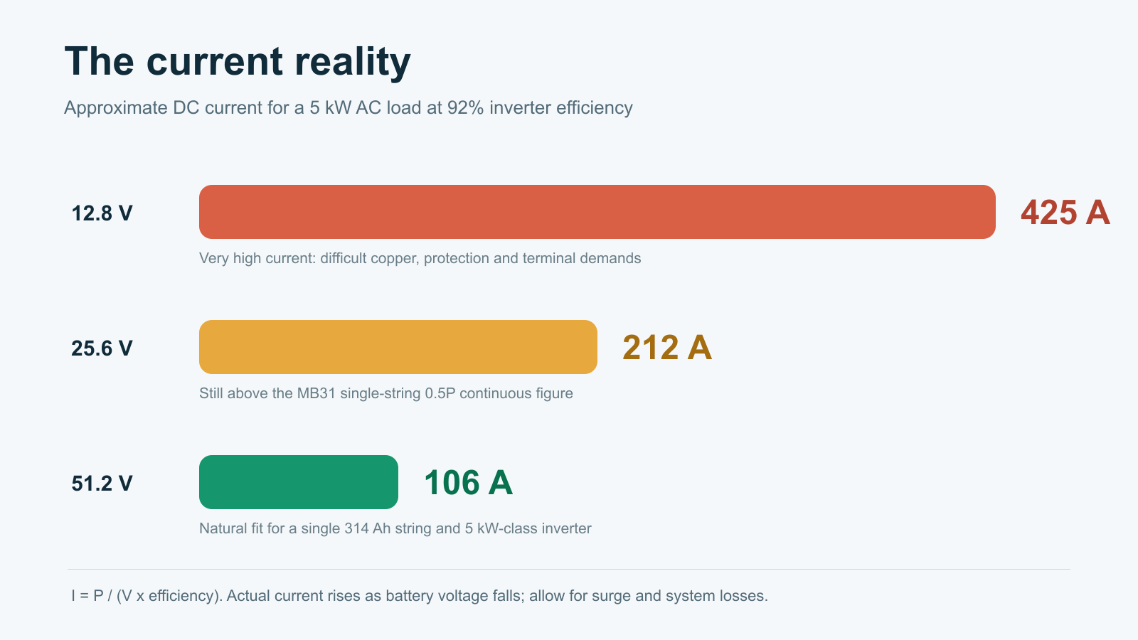
DC current = AC load watts / (battery voltage x inverter efficiency)

At 92% inverter efficiency, a 5kW load requires approximately 425A from a 12.8V pack, 212A from a 25.6V pack and 106A from a 51.2V pack. Actual current rises as battery voltage falls, and surge, inverter self-consumption and conductor losses add more.

Comparison of current required for a 5kW inverter load at 12.8V, 25.6V and 51.2V
The same inverter load becomes much easier to manage as system voltage rises.
4S

12.8V / 4.02kWh

Best for modest RV, marine and small off-grid loads. A single MB31 string is not a sensible route to a continuous 3-5kW inverter.

8S

25.6V / 8.04kWh

A practical middle ground for medium off-grid systems and roughly 2-3kW inverter loads when the complete current design supports it.

16S

51.2V / 16.08kWh

The hero build for home storage and modern inverter systems. It naturally suits a 5kW-class Deye, Victron or Growatt installation.

EVE MB31 314Ah cells configured as 4S, 8S and 16S LiFePO4 battery packs
Nominal energy is nominal voltage multiplied by 314Ah. The enclosure, BMS, protection and copper add substantial weight.
Important cell limit: the reviewed MB31 specification lists 0.5P maximum continuous charge and discharge power at 25°C. For a 314Ah, 3.2V cell, this corresponds to about 157A and 502W per cell under those conditions. A 200A BMS does not upgrade the cell, cable, terminal, busbar or fuse.

2. Why the EVE MB31 314Ah?

The MB31 is a strong all-round energy-storage cell. EVE lists 314Ah nominal capacity, 3.2V nominal voltage, 1004.8Wh nominal energy, approximately 5.6kg weight and 0.5P/0.5P standard charge/discharge capability.

Its greatest DIY advantage is not only capacity. The 280-314Ah prismatic-cell format has a mature ecosystem of enclosures, busbars, insulation, restraint systems and BMS hardware. That makes a 16-cell, 16kWh pack easier to support than many newer oversized cell formats.

For a broader comparison, read our EVE MB31 vs LF334 vs REPT 345Ah decision guide.

3. Match the BMS to the actual pack

The BMS must match the chemistry, series count, normal current, surge behaviour, temperature requirements and inverter communication method.

PackJK selectionImportant limitation
4S / 12.8VA genuine 4S-capable JK modelThe reviewed JK PB1/PB2 16S family does not cover 4S. See our JK 4-8S first-start guide.
8S / 25.6VA correctly rated 8S JK, or a compatible PB model after firmware/protocol verificationThe reviewed PB manual covers 7-16S electrically, but inverter communication at 24V still needs confirmation for the exact hardware.
16S / 51.2VJK PB inverter BMS matched to the required currentConfirm hardware revision, firmware, CAN/RS485 protocol and pinout for the actual inverter.

Never choose a BMS only because its headline current rating matches the inverter. A 200A BMS can still be the wrong choice if the cell, terminal, conductor, busbar, enclosure or fuse cannot safely support the intended current.

4. Parts and tools

Cells, BMS and monitoring

  • 4, 8 or 16 traceable EVE MB31 314Ah cells
  • JK BMS matched to the exact series count, current and communication requirement
  • All specified cell and BMS/MOS temperature sensors
  • Compatible JK display/interface board where required
  • Verified CAN or RS485 cable built from the exact two product pinouts

Mechanical assembly and insulation

  • Rigid enclosure with service access and protected conductor entries
  • Engineered restraint with flat end plates
  • Cell-to-cell insulation and a non-conductive base
  • Terminal and busbar covers
  • Strain relief, abrasion protection and secure BMS mounting

The reviewed EVE specification lists a recommended cell compression force of 3000-7000N and an instantaneous maximum of 10000N. This is force across the cell face, not threaded-rod torque. Do not invent a bolt torque without an engineered clamp geometry and measurement method.

Power path and tools

  • Busbars and terminal hardware suited to the actual cell variant
  • DC-rated fuse with suitable voltage rating, interrupt rating and time-current behaviour
  • Load-rated DC disconnect where required by the design
  • Conductors, lugs and supports sized for the installation method
  • Pre-charge resistor and switching method designed for the inverter input capacitance
  • CAT-rated multimeter, insulated probes and insulated tools
  • Calibrated torque wrench or screwdriver
  • Proper lug crimper and cable cutter
  • Thermal camera for staged-load commissioning

EVE specifies a maximum pole torque of 6N·m in the reviewed MB31 datasheet. Confirm that value against the actual terminal variant, adapters and fasteners supplied. Use a calibrated tool and record the final result.

5. Inspect the cells before assembly

Do not assemble first and discover a problem later. Record the supplier, batch/QR information, physical condition, resting voltage and consistently measured internal resistance for every cell. Capacity-test if that is part of the acceptance plan.

Quarantine any cell with a dent, swelling, leak, corroded or damaged terminal, abnormal voltage or unexplained measurement outlier. A severely over-discharged cell should not be “recovered” as part of a public tutorial.

6. Top balancing: choose a controlled method

Top balancing is a commissioning process, not a ritual that must be repeated routinely. Two defensible approaches are common:

  1. Parallel top balance before assembly: bring the cells to the same upper state of charge with a current-limited bench supply, verified polarity, temperature monitoring and continuous supervision.
  2. Assemble and commission slowly: construct the series pack, verify every sense connection, charge at low controlled current and allow the active balancer to correct the upper-curve spread.

Do not use a “set the supply and walk away” method. The process needs current limiting, supervision, a clear termination criterion and respect for EVE’s 3.65V absolute charge limit. For a dedicated walkthrough, see How to Top Balance LiFePO4.

7. Mechanical assembly

  1. Prepare a clean, dry, non-conductive bench and remove jewellery.
  2. Confirm cell orientation against a printed series map.
  3. Install cell-to-cell insulation before fitting busbars.
  4. Place cells into the restraint system without lifting from the terminals.
  5. Apply controlled, even restraint within the manufacturer’s force limits.
  6. Install one busbar at a time while neighbouring terminals stay covered.
  7. Use only an approved method to prepare mating surfaces.
  8. Tighten with the correct sequence and calibrated torque tool.
  9. Apply a torque mark and replace the terminal cover immediately.
  10. Compare measured total series voltage with the sum of the individual cells.

Never rest the BMS, tools, fasteners or loose busbars on exposed cells.

8. Verify every BMS sense lead before connection

A misplaced balance lead can damage the BMS or create a short through the harness. Wire colour alone is not proof.

  1. Leave the BMS sense connector unplugged.
  2. Attach the harness to the cell string in the exact order shown in the manual.
  3. Measure each adjacent step at the unplugged connector: B0-B1, B1-B2 and onward should each show one cell voltage with correct polarity.
  4. Measure cumulatively from B0 to every successive pin. Voltage should rise by one cell at each step.
  5. Stop if any step is negative, zero or close to two cell voltages.
  6. Verify B-, P-, display, communication and temperature connections.
  7. Only insert the sense connector after an independent recheck.

9. The BMS is not the fuse

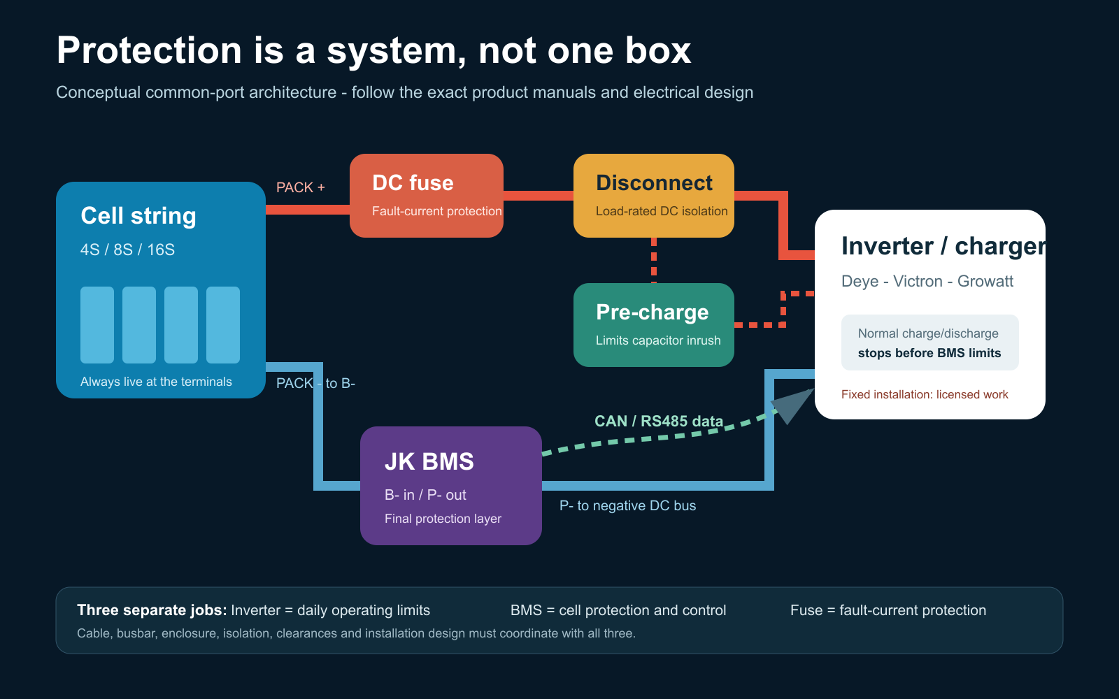
Conceptual LiFePO4 battery system showing cell string, BMS, fuse, disconnect, pre-charge and inverter
The inverter, BMS and fuse perform different jobs and must be coordinated with the rest of the design.

In a common-port MOSFET arrangement, cell-string negative connects to BMS B-, and BMS P- connects to the negative DC bus. Cell-string positive goes through the engineered positive protection and isolation path to the DC bus. Follow the exact JK manual for the hardware being used.

The fuse protects against fault current. It requires an adequate DC voltage rating, interrupt capacity and time-current relationship with the conductors and equipment. A pre-charge circuit limits inverter-capacitor inrush before the main path is closed. Read our discussion of 48V battery circuit breakers and Class T fuses.

An RJ45 connector does not guarantee an Ethernet pinout. Verify both ends of every JK-to-inverter communication cable and continuity-test it before connection.

10. Conservative JK settings for an MB31 pack

The best settings make the inverter stop normal operation first, keep the BMS as the last-resort guardrail and leave the fuse to clear serious fault current.

FunctionStarting valuePurpose
ChemistryLiFePO4Select before entering other values.
Cell count4, 8 or 16 as physically builtVerify from the harness and cumulative voltage.
Capacity314Ah or measured usable capacityEstablishes the coulomb-counter baseline.
Balance startAbout 3.40V/cellBalances on the upper curve rather than chasing mid-curve load sag.
Balance delta10-15mVAvoids hunting over tiny dynamic differences.
Controlled charge ceiling3.55V/cellLeaves margin below EVE’s 3.65V maximum.
Cell OVPAbout 3.60VLast-resort high-cell protection.
OVP recoveryAbout 3.45VProvides useful hysteresis.
SOC 100%3.50V/cellSynchronises the fuel gauge; it is not the charge cutoff.
Float / maintenance3.40V/cell if requiredAvoids holding the pack at its charge ceiling.
Cell UVP2.80V/cellHard BMS cutoff. Do not design routine cycling to 2.5V.
UVP recoveryAbout 3.00-3.05V/cellCoordinate with restart behaviour.
Charge low-temperature stop0°CMatches the lower end of EVE’s listed charge range.
Charge low-temperature recovery3-5°CPrevents cycling at freezing point.
Emergency modeOFFIt overrides normal protections and is not an operating mode.

Pack-voltage equivalents

PackCharge at 3.55V/cell100% sync at 3.50V/cellFloat at 3.40V/cellBMS UVP at 2.80V/cell
4S14.2V14.0V13.6V11.2V
8S28.4V28.0V27.2V22.4V
16S56.8V56.0V54.4V44.8V
Normal low-voltage operation: set the inverter’s routine low-SOC or low-voltage stop above 2.80V/cell, allowing for voltage sag at the design load. The 2.80V JK value is a hard last-resort cutoff, not the normal end of every cycle.

Do not simply enter the BMS’s maximum current as the charge/discharge limit. The operational current must respect the MB31 continuous limit, conductor and busbar ampacity, terminal temperature, fuse coordination and inverter behaviour. Over-current delays, short-circuit delay and smart-sleep behaviour must be verified against the exact JK firmware.

LiFePO4 does not need lead-acid-style float charging. If an inverter requires a float field, 3.40V/cell is a conservative maintenance value for this project. See our separate LiFePO4 float-voltage guide.

11. Deye, Victron and Growatt SPF integration

Closed-loop CAN or RS485 communication can allow the BMS to report SOC, alarms, requested charge voltage, charge-current limit and discharge-current limit. It does not remove the need for safe fallback settings.

Deye / SunSynk

  • Record the full JK and Deye model, hardware revision and firmware.
  • Verify CAN versus RS485 and both connector pinouts.
  • Select the matching JK inverter protocol and lithium/BMS mode.
  • Confirm SOC, requested voltage, current limits and alarms on both devices.
  • Disconnect communication in a controlled test and prove the intended fallback/fault response.

Victron

A Victron system may use a GX device, DVCC and compatible CAN-bus integration, or it may run open-loop. Do not assume native support until the exact JK firmware/protocol and Victron architecture have been tested. Existing site references include connecting a JK inverter BMS to Victron and the Victron Multi RS 48/6000 JK CAN example.

Growatt SPF

Growatt SPF is a family, not one universal protocol. Confirm the full inverter model and firmware, CAN/RS485 requirement, battery protocol, pinout, lithium-menu selection and safe open-loop fallback values.

12. First power-up and commissioning

Before energising

  • Cell model, quantity and polarity match the drawing.
  • No damaged or quarantined cell is installed.
  • Restraint and insulation are complete.
  • Every busbar and terminal is torqued, marked and covered.
  • Every adjacent and cumulative sense voltage is correct.
  • B-/P-, fuse, disconnect, conductor and pre-charge designs have been checked.
  • Temperature probes are installed at representative locations.
  • The inverter is isolated from AC, grid and PV as required by its shutdown procedure.

Controlled commissioning sequence

  1. Wake the BMS without the inverter load and compare every cell reading with the multimeter.
  2. Check all temperature sensors and alarm states.
  3. Verify charge/discharge switching and the configured limits.
  4. Pre-charge the inverter using the designed method.
  5. Close the main DC path only after the voltage difference has fallen to the design criterion.
  6. Begin at low power and compare BMS, external meter and inverter readings.
  7. Increase load in planned steps while recording cell delta, voltage drop and temperatures.
  8. Thermally inspect terminals, busbars, BMS and conductors after a meaningful load soak.

Stop for a hot connection, rising cell temperature, swelling, abnormal smell or sound, unstable voltage, unexplained cell divergence or a mismatch between instruments. Do not deliberately short the pack or force cells beyond safe limits to “test” protections for a video.

13. Parallel packs need separate protection

Parallel packs are separate energy sources. Each pack needs a compatible BMS and normally its own branch fuse and isolation, connected to an engineered common bus.

  • Match chemistry, series count and operating voltage.
  • Bring pack voltages close before connection.
  • Use an engineered current-sharing/busbar arrangement.
  • Configure unique BMS addresses where required.
  • Confirm how total charge and discharge limits reach the inverter.
  • Prove that one isolated pack cannot overload the remaining pack.

Never connect packs at significantly different voltages and expect the BMS to control equalisation current.

14. A good battery finishes with documentation

A battery is not finished merely because it turns on. Keep a permanent pack record containing:

  • one-line diagram and cell-series map
  • cell and BMS datasheets
  • final settings and firmware versions
  • cell inspection, torque and thermal-test records
  • fuse, disconnect, conductor and pre-charge details
  • shutdown, restart and emergency procedures
  • SDS location, maintenance schedule and alarm meanings

Future checks should review enclosure condition, moisture or pests, event logs, cell-delta trends, terminal condition and temperature under a known load. Do not casually retorque live terminals.

The build philosophy in one minute

  1. Choose voltage from current and inverter power.
  2. Keep normal continuous current within the cell and complete-system limits.
  3. Inspect and document every cell before assembly.
  4. Restrain, insulate, torque and cover the pack correctly.
  5. Verify every balance lead with a meter before connecting the BMS.
  6. Make the inverter stop normal operation before the BMS guardrails.
  7. Use 3.55V/cell charge, 3.50V/cell SOC sync, 3.40V/cell float if required and 2.80V/cell only as the hard low-voltage cutoff.
  8. Commission in controlled stages and record the thermal result.

Technical references

For the Australian installation boundary, also read Safe Installation of LiFePO4 Batteries in Australia.

Lithium Battery-school Blog
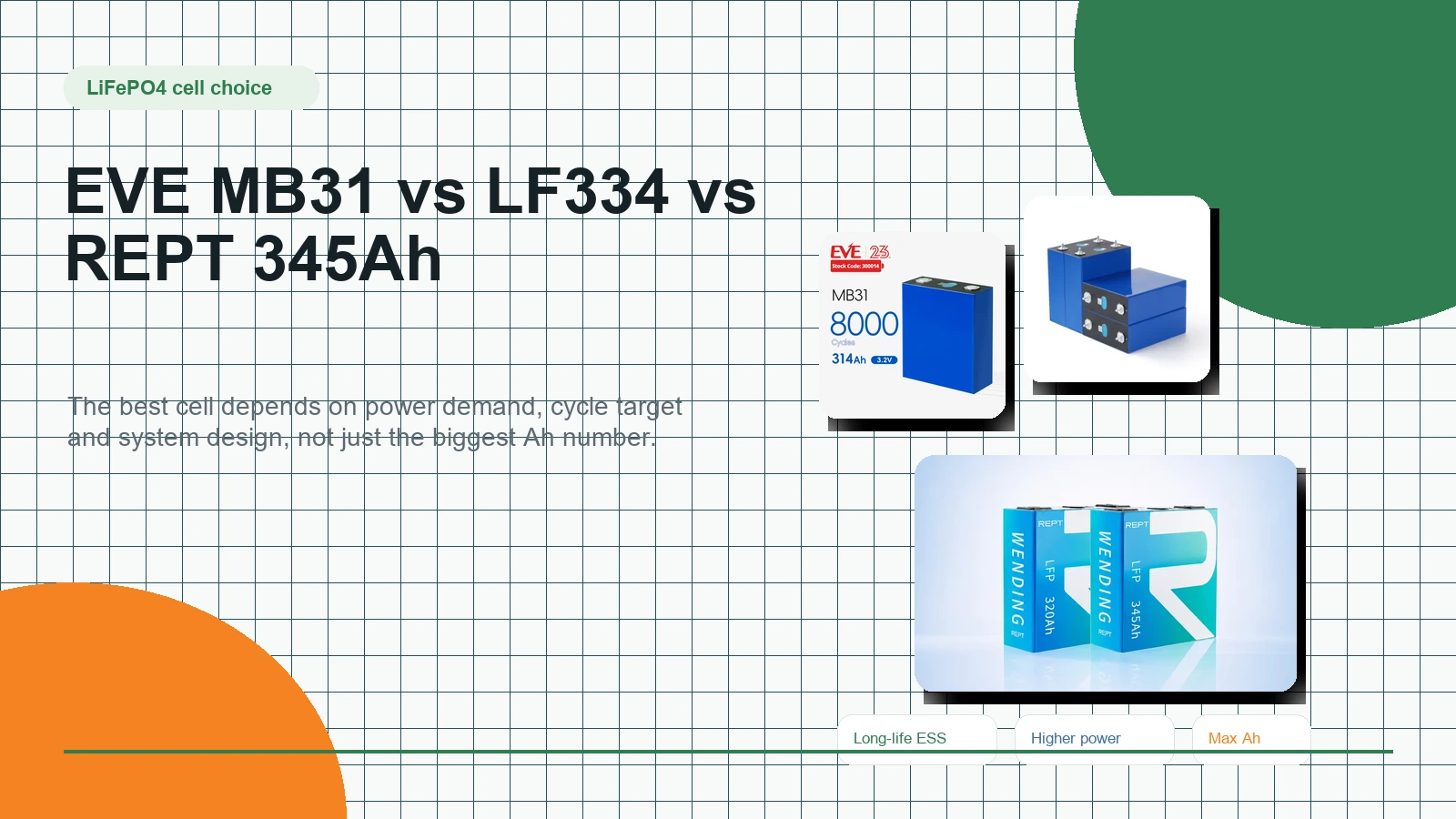
EVE MB31 vs EVE LF334 vs REPT 345Ah: Which LiFePO4 Cell Should You Choose?

LiFePO4 cell buyer’s guide · updated 2026

Choose the cell for the job—not the biggest Ah number.

EVE MB31, EVE LF334 and REPT 345Ah can all build an excellent battery. The right choice comes down to the balance between stored energy, current demand, pack voltage and how hard the battery will work.

EVE MB31, EVE LF334 and REPT 345Ah LiFePO4 cells compared by capacity, power and storage use case
3 good cells. Three different strengths.
314 AhEVE MB31 · balanced long-life ESS choice
334 AhEVE LF334 · higher-output option worth considering
345 AhREPT CB84 · maximum energy for gentler storage duty

The quick answer

Start with the way the battery will work.

Capacity matters, but the battery’s voltage, inverter size and expected current decide whether that capacity can be used comfortably.

1

EVE MB31

The safest all-round recommendation for home solar, off-grid and daily-cycling ESS builds with moderate current demand.

Choose it when: proven storage duty and a balanced design matter most.

2

EVE LF334

The cell to look at when the pack needs more current headroom. It is especially relevant for demanding 12V and 24V builds, mobile power and larger inverter loads.

Choose it when: output capability matters as much as stored energy.

3

REPT 345Ah

The most stored energy per cell in this comparison, well suited to large banks and longer-duration storage designed around a gentler discharge rate.

Choose it when: maximum capacity and value matter more than high current from one string.

Side-by-side comparison

Similar size class. Different design priorities.

Use this as a buying map, then confirm the exact continuous-current, pulse-current, compression and cycle-test conditions for the batch being supplied.

CellNominal energy per cellApprox. 16S energyBest fitMain caution
EVE MB31 314Ahabout 1.00 kWhabout 16.1 kWhLong-life ESS, home solar, off-grid and commercial storageNot the first choice for very high current from a small pack
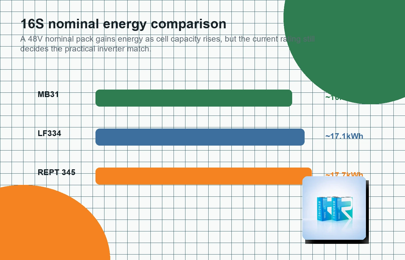
EVE LF334 334Ahabout 1.07 kWhabout 17.1 kWhHigher-output 12V, 24V and 48V builds, RV, marine and mobile powerVerify continuous versus pulse ratings against the exact batch datasheet
REPT 345Ah CB84about 1.10 kWhabout 17.7 kWhLarge solar banks, long-duration backup and lower-rate ESSOne small string may not suit a large inverter running continuously
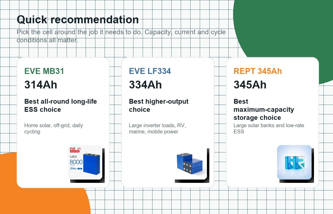
Quick recommendation cards for EVE MB31, EVE LF334 and REPT 345Ah LiFePO4 cells
MB31 is the balanced storage choice, LF334 adds power headroom, and REPT 345Ah maximises energy per cell.

Why Ah alone is misleading

A bigger fuel tank does not automatically mean a stronger engine.

Ah tells you how much charge a cell stores. It does not tell you how quickly the cell should deliver that charge, how much heat the pack will create, or whether the BMS, busbars and cabling can support the load.

Pack voltage changes everything

A 3000W inverter on 12V can draw well over 230A before losses. At 48V, the same power needs roughly one quarter of the current.

C-rate needs context

Standard, continuous and pulse ratings are not interchangeable. Use the exact supplied-cell datasheet when setting charge, discharge and BMS limits.

The whole pack carries the load

Cell rating is only one limit. BMS current, connections, busbars, cable size, compression, cooling and inverter surge behaviour all matter.

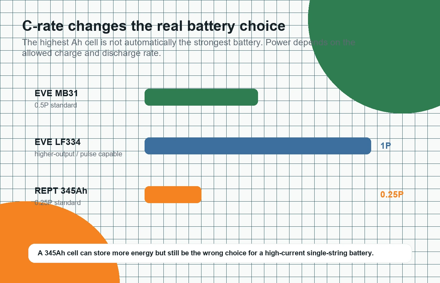
C-rate chart comparing EVE MB31, EVE LF334 and REPT 345Ah LiFePO4 cells
C-rate changes the practical battery choice. More Ah does not always mean more usable inverter power.

Why LF334 deserves a closer look

Current headroom can be worth more than a headline cycle number.

The LF334 is easy to overlook if you compare only ESS cycle claims or cost per Ah. Its real appeal is a more power-oriented role: high-load 12V systems, mobile and marine builds, and batteries expected to support larger inverters from a single string.

That does not make it automatically better than MB31. It makes it better suited to a different duty cycle. If a conservative ESS cell leaves too little margin at the current your build requires, LF334 is genuinely worth considering.

LF334 makes sense when…

the battery voltage is low, inverter load is high, surge performance matters, or you want more current headroom without adding parallel strings.

Keep the claim honest

A high pulse figure must not be presented as a continuous rating. Confirm the exact supplied batch and design the BMS and conductors around the verified limit.

16S nominal energy comparison for EVE MB31, EVE LF334 and REPT 345Ah LiFePO4 cells

Choose by system

12V, 24V and 48V can change the answer.

The same inverter power creates very different current at different battery voltages. That is why a power-oriented cell can be valuable in a compact 12V build, while a moderate-rate ESS cell becomes much more practical in a 48V pack.

12V

High current

Large inverters can demand hundreds of amps. LF334 deserves serious consideration, along with carefully sized BMS, busbars and cabling.

24V

Middle ground

Current is more manageable, but mobile and inverter-heavy systems can still benefit from added output headroom.

48V

Storage friendly

Lower current for the same power makes MB31 and REPT-style storage cells easier to use in appropriately sized banks.

Compare live products

Check the cells, stock and current pricing.

Product details below come directly from WooCommerce, so the links and current store information remain useful as the guide ages.

Before building: confirm the supplied batch datasheet and do not set charge or discharge limits from a general comparison article alone.

LiFePO4 cell finder

Choose by discharge time.

How quickly does the battery need to deliver its stored energy? Pick the closest duty class below: one hour for high power, two hours for balanced storage, or four-plus hours for a very large long-duration bank.

More power per cellMore runtime and capacity
1 hour
Around 1C duty
High current

Choose EVE LF334

For batteries that must deliver a lot of power from each cell string.

  • Large inverter loads
  • High-power 12V or 24V systems
  • Compact or single-string builds
View EVE LF334
2 hours
Around 0.5C duty
Balanced middle

Choose EVE MB31

For the many systems that sit between maximum power and maximum capacity.

  • General home and off-grid ESS
  • Moderate inverter demand
  • Balanced daily-cycling storage
View EVE MB31
4+ hours
Around 0.25C duty
Long-duration storage

Choose REPT 345Ah

For a very large battery designed around gentle current and maximum stored energy.

  • True off-grid living
  • Multi-day autonomy without sun
  • Large 48V or parallel-string banks
View REPT 345Ah

Important: “1 hour”, “2 hours” and “4 hours” describe the approximate discharge-rate class, not a promise that the battery stops after that time. A large REPT bank running lighter real-world loads can provide days of autonomy. Always confirm the exact supplied-cell datasheet and size the complete battery around inverter power, usable kWh, BMS, wiring and charging limits.

Still choosing between two cells?

Tell us the pack voltage, inverter size, target capacity and whether the battery is for mobile power, off-grid use or daily home storage. We can help narrow the choice before you order.

Technical notes

This page is practical buying guidance based on the current EVE MB31, EVE LF334 and REPT 345Ah product information and the distinction between energy-focused ESS duty and higher-output battery duty. Approximate kWh figures use 3.2V nominal voltage and are not usable-energy guarantees. Always confirm continuous current, pulse current, compression, operating temperature and cycle-test conditions against the exact datasheet for the batch being supplied.

Blog Lithium Battery-school
How to Start a JK BMS (4-8S) for the First Time – 4S (12V) Setup

If the JK BMS is not turning on when first connected, follow these steps to troubleshoot and properly power it up.

1. Check the Wiring Connections

  • Ensure the balance leads are connected correctly
    • The B- lead should be connected to the main negative of the battery pack.
    • The balance wires must be connected in the correct sequence:
      • B0 (Black wire) → Main negative terminal of the first cell
      • B1 → Positive terminal of Cell 1
      • B2 → Positive terminal of Cell 2
      • B3 → Positive terminal of Cell 3
      • B4 → Main positive terminal of the battery pack

2. Verify Cell Voltages

  • Measure the voltage between each balance wire using a multimeter.
  • Ensure all cell voltages are within a reasonable range (typically 3.2V – 3.6V per cell).
  • If any cell voltage is missing or significantly different, the BMS may not power on.

3. Check the Main Power Connection

  • B- Wire (Main Negative): Ensure the thick B- wire is securely connected to the main negative of the battery pack.
  • P- Wire (Output Negative): This connects to the load/charger and should not be used for powering the BMS initially.

4. Manually Activate the BMS

  • Some JK BMS units require manual activation if they don’t turn on automatically.
    • Try plugging in a charger (even briefly) to the battery terminals to “wake up” the BMS.
    • Alternatively, hold down the power/reset button (if available) for 3-5 seconds.
    • If you dont have the power button, consider sourcing one

5. Check if the BMS is Drawing Current

  • Use a multimeter in DC current mode to check if any current is flowing through the BMS.
  • If the BMS is drawing zero current, it may indicate a wiring issue or a defective unit.

6. Test Communication with the App

  • Download the JK BMS App on a smartphone.
  • Turn on Bluetooth and try scanning for the device.
  • If the BMS does not appear, it is still off or not receiving power.

7. Inspect for Factory Sleep Mode

  • Some BMS units are shipped in a factory sleep mode, requiring a charger or an external power source to turn on.

8. Reset the BMS

  • If all else fails, disconnect all connections for 1-2 minutes, then reconnect everything carefully.

Final Check

  • Once the BMS powers on, verify that all cell voltages are detected correctly in the app.
  • If issues persist, check the BMS documentation or test with another BMS to rule out a faulty unit.

STILL NOT WORKING? Its probably in sleep mode

If the JK BMS is in sleep mode and does not have a power button, here are all possible ways to wake it up:


1. Connect a Charger to the Battery

  • Most common method: Connecting a charger to the battery terminals will usually wake up the BMS.
  • Plug a LiFePO4-compatible charger (or a power supply) into the battery’s main terminals (B+ and B-).
  • Even a brief connection (a few seconds) might be enough to turn the BMS on.

2. Connect a Charger to the Load Side (P+ and P-)

  • If charging via the battery terminals does not work, try connecting the charger to the load terminals (P+ and P-).
  • Some JK BMS models wake up when voltage is applied here.

3. Apply a Small Load Across P+ and P-

  • Some JK BMS units wake up when they detect a current draw.
  • Connect a small 12V load (e.g., a 12V light bulb or small resistor) across P+ and P- for a few seconds.

4. Jumpstart the BMS Using a Resistor or Wire

  • Take a resistor (~1kΩ – 10kΩ, 0.5W or higher) or a jumper wire and temporarily connect:
    • B+ (battery positive) to P+ (load positive)
    • B- (battery negative) to P- (load negative)
  • This creates a tiny voltage differential, which can wake the BMS up.

5. Disconnect and Reconnect the Balance Leads

  • Sometimes, disconnecting and then reconnecting the balance leads (B0-B4) in the correct order can trigger the BMS to power on.
  • Steps:
    1. Disconnect the balance connector from the BMS.
    2. Wait 1-2 minutes.
    3. Reconnect it in the correct sequence (B0 → B1 → B2 → B3 → B4).

6. Use a Bench Power Supply to Apply Voltage to B+ and B-

  • If the BMS is completely unresponsive, try applying a small amount of voltage from a bench power supply.
  • Set the power supply to 12-14V, and briefly connect it to B+ and B-.
  • This simulates a charger and can often wake up the BMS.

7. Check for a Reset Pin on the BMS Board

  • Some JK BMS units have an internal reset pin or pads that, when shorted for a second, will wake the unit.
  • If comfortable opening the BMS case, check for labeled pads (like RST or SW) and try shorting them momentarily.

Final Step: Replace the BMS

If none of these methods work, the BMS might be defective or damaged. Testing with another BMS will confirm whether the issue is with the battery or the unit itself.

Lithium Battery-school EV Engineering
Understanding Why Limiting Charging Rates Extends the Lifespan of Lithium Iron Phosphate (LFP) Batteries

Understanding Why Limiting Charging Rates Extends the Lifespan of Lithium Iron Phosphate (LFP) Batteries

As electric vehicle (EV) and energy storage enthusiasts continue exploring the best lithium-ion battery technologies, Lithium Iron Phosphate (LFP) has emerged as one of the most reliable choices. Known for its stability, high safety profile, and impressive cycle life, LFP has become the preferred option for many EV manufacturers, including Tesla, and is widely used in off-grid energy storage solutions. However, while LFP cells excel in durability, there’s a key factor to keep in mind for achieving optimal performance and longevity: limiting the charging rate.

Recent research on the LFP battery cells from a Tesla Model 3 has shed light on the importance of controlled charging. The study revealed that even high-quality LFP batteries experience significant wear and reduced lifespan when charged at rates exceeding 0.5C. By limiting the charging rate to 0.5C or less, these batteries can last significantly longer, providing multiple times the lifespan of those charged at higher rates. This article delves into these findings, explaining why lower charging rates are crucial for extending the life of your LFP batteries.

https://ars.els-cdn.com/content/image/1-s2.0-S001346862301513X-gr1.jpg

Cell shows is a 161.5 Ah prismatic flat wound hardcase cell from a state-of-the-art Tesla Model 3 in 2021-2023+ Chinese made Long Range version. Australian Long range RWD.

What Does “0.5C Charging Rate” Mean?

Before diving into the research findings, let’s clarify what the term “0.5C” means in the context of battery charging. The “C-rate” refers to the rate at which a battery is charged or discharged relative to its capacity. A 1C rate would mean charging a battery at a current that would fully charge it in one hour. A 0.5C rate, in turn, means charging it at half that current, or over two hours. Therefore, for a 100Ah battery, a 0.5C rate would be a 50A current.

The Study’s Findings: Why 0.5C is the Ideal Limit for LFP Batteries

The in-depth study of Tesla’s prismatic LFP battery cells showed that the battery’s performance and lifespan were significantly influenced by charging rates. Here’s a summary of the key findings:

  1. Increased Degradation at Higher C-Rates: The study found that at charging rates higher than 0.5C, lithium plating—a process where lithium ions accumulate unevenly on the anode—was more likely to occur. This plating can result in a range of performance issues, including reduced capacity, increased internal resistance, and even the risk of short circuits.
  2. Extended Lifespan with Lower Rates: When the battery was charged at 0.5C or lower, there was a noticeable reduction in wear and tear, significantly extending the overall lifespan of the cell. For users in the EV and solar storage markets, this insight underscores the value of slower, steady charging cycles. Slower charging reduces strain on the battery’s materials, preventing chemical and mechanical degradation that shortens its life.
  3. Why Lower Charging Rates Matter: Lower rates help avoid lithium plating, which tends to happen when the anode can’t absorb lithium ions quickly enough, leading to uneven distribution and increased risk of failure. By charging at a rate that allows for a uniform distribution of lithium ions, the battery retains its capacity and efficiency for longer.

The Case for Lower Charging Rates in Everyday Applications

For EV owners, energy storage users, and anyone relying on LFP batteries, these findings emphasize the importance of charging at a controlled rate. Charging at 0.5C or less not only maximizes battery lifespan but also enhances long-term energy efficiency. Let’s look at how this plays out in practical scenarios:

  • EV Charging: While some high-end EVs are capable of ultra-fast charging, LFP batteries used in these vehicles often limit charging speeds to avoid accelerated wear. Tesla, for example, carefully controls the charging rates in its vehicles equipped with LFP packs, balancing quick charging with long-term durability. For individual users, this means that opting for slower home-charging setups can actually help extend the life of their vehicle’s battery.
  • Solar and Off-Grid Energy Storage: In solar storage applications, battery health is critical for reliability and long-term cost savings. Charging at rates below 0.5C not only optimizes the lifespan of LFP cells but also ensures consistent performance over years, allowing off-grid users to get the most out of their investment. Since off-grid storage systems are typically designed to cycle batteries daily, maximizing the number of cycles through careful charging can make a significant difference.

How Lower Charging Rates Affect Battery Lifespan

The benefits of lower charging rates are especially apparent when considering the relationship between charging rate and battery cycle life. Studies have shown that LFP batteries can achieve thousands of cycles—up to 10,000 or more—when charged and discharged at a 0.5C rate or lower. In contrast, higher charging rates significantly reduce the number of cycles before the battery’s capacity begins to degrade. For example, charging at a rate of 1C or more can lead to premature aging, resulting in a battery that may last only a few thousand cycles.

A simplified way to look at this is that reducing the charging rate reduces stress on the battery, which keeps it in a healthier state longer. Each charge cycle at a controlled rate is a gentler cycle, allowing the battery materials to hold up over time. This means less frequent replacements, lower maintenance costs, and better long-term performance.

Understanding the Trade-Offs: Speed vs. Longevity

While faster charging can be convenient, especially in situations where quick turnaround is needed, it comes at the cost of lifespan. Here’s a quick comparison of the trade-offs:

Charging RateLifespan ImpactBest Use Cases
>1CSignificantly ReducedQuick charging needs, emergency situations
0.5COptimal LongevityRoutine EV charging, solar energy storage, daily cycling
<0.5CMaximum LifespanOff-grid storage, backup power systems where longevity is prioritized

Conclusion: Extending Your LFP Battery’s Lifespan Through Controlled Charging

For those seeking reliable, long-lasting LFP battery performance, charging at or below 0.5C is essential. Whether for an EV, solar storage system, or other energy solution, following this guideline can dramatically extend the lifespan and overall efficiency of your batteries.

In today’s fast-paced world, it’s tempting to charge everything as quickly as possible, but with LFP batteries, patience truly pays off. Taking a steady approach to charging can mean the difference between a battery that lasts years and one that requires early replacement. By embracing lower charging rates, we can get the most out of these resilient LFP batteries—optimizing performance, reducing environmental impact, and ultimately saving on costs in the long run.

Sources


https://www.sciencedirect.com/science/article/pii/S001346862301513X

https://www.linkedin.com/pulse/battery-disassembly-characterization-power-square-case-lfp-link-sun-cnx4c?trk=public_post_feed-article-content

News Manufacturers
Comprehensive Guide to Battery Management Systems (BMS): Comparing JBD, JK, PACE, Daly, and More

In today’s rapidly expanding energy storage market, Battery Management Systems (BMS) play a critical role in the health, safety, and performance of lithium batteries. Whether you are building a battery for a solar setup, electric vehicle (EV), or DIY energy storage system, choosing the right BMS is essential for managing battery performance, extending lifespan, and protecting against potential hazards.

This guide will delve into some of the most popular and well-regarded BMS options available in the market, including JBD, JK, and Daly, analyzing their features, reliability, and overall performance. We’ll also highlight the pros and cons of each system to help you make an informed decision based on your specific requirements.

What is a Battery Management System (BMS)?

A BMS is an electronic system that manages a rechargeable battery, such as lithium-ion or lithium iron phosphate (LiFePO4), by controlling key functions like charging, discharging, temperature, and overall safety. The BMS ensures that the battery operates within safe limits and helps prolong its lifespan by balancing the cells and protecting against issues like overvoltage, undervoltage, and overheating.

Popular BMS Brands Overview

The BMS market is vast, with many different manufacturers offering various models ranging from budget-friendly basic protection systems to advanced smart BMS options with sophisticated features like Bluetooth connectivity and active balancing. Let’s explore some of the most popular brands:


1. JBD BMS (Jiabaida BMS)

Overview:
JBD is a popular choice among DIY battery builders and professionals alike. Known for its reliability and affordability, JBD offers a wide range of BMS products suitable for everything from small battery packs to large energy storage systems. It also features smart BMS options with Bluetooth, providing real-time monitoring and control through mobile apps.

Support for Victron, DEYE, Growatt and many other inverters.

Key Features:

  • Available in 12.8V to 48V(51.2V) configurations, with various amp ratings.
  • Both Smart BMS with Bluetooth connectivity for monitoring battery status via an app and Regular BMS, set and forget!
  • Robust passive and active balancing models to keep cell voltages even.
  • Comprehensive protection against overcharge, over-discharge, and over-temperature.
  • Configurable parameters via PC software or mobile app.

Pros:

  • Cost-effective with very reliable performance.
  • Smart features like Bluetooth monitoring and mobile app control.
  • Flexible configuration options.
    Excellent Accuracy for SOC calculations
  • Available in high current ratings, suitable for large packs.
  • Regular firmware updates improve functionality.

Cons:

  • Slightly more complex to set up compared to simpler BMS units.
  • Bluetooth connection range can be limited.
  • Lack of detailed user manual support for first-time users.

Best For:
JBD BMS is well-suited for both DIY enthusiasts and professional battery builders who need reliable, affordable BMS with smart monitoring features. Ideal for medium to large battery packs in solar, RV, and EV applications.


2. JK BMS (JiKong BMS)

Overview:
JK BMS is one of the most advanced BMS systems on the market, especially popular among energy storage professionals. It is known for its robust features, including active balancing, high customization options, and detailed data monitoring. JK BMS is highly regarded for its accuracy, durability, and flexibility, making it ideal for large-scale and critical battery systems. Support for Victron, DEYE, Growatt and many other inverters.

Key Features:

  • Active balancing (dynamic cell balancing) ensures cells are equalized during operation.
  • Bluetooth connectivity for real-time monitoring via a mobile app.
  • Configurable protection parameters for precise control over charging and discharging.
  • Software is good, but not perfect, and support has been poor in 2024 for the new model

Pros:

  • Excellent active balancing capabilities reduce cell degradation and extend lifespan.
  • Detailed monitoring and data logging for precise control.
  • Widely customizable for different applications off-grid systems, and commercial setups.
  • Rugged design with high current and voltage tolerance.
  • Good accuracy for professional energy storage projects.

Cons:

  • More expensive than basic BMS units.
  • Higher learning curve for those new to BMS systems.
  • Requires more time to set up and configure.
  • Quality of materials may be lower, than JBD
  • Software has been buggy.

Best For:
JK BMS is the go-to choice for large-scale, critical energy storage applications where active balancing and precise control are necessary. It is ideal for professional setups, commercial energy storage, and high-performance EVs.


3. Daly BMS

Overview:
Daly BMS is another popular option, especially in the DIY space, due to its affordability and basic functionality. Daly BMS is often used for simple battery systems that don’t require the advanced features seen in more expensive systems like JK or JBD. It offers basic protection for lithium batteries, making it suitable for small energy storage systems or low-demand applications.

Key Features:

  • Basic protection: overvoltage, undervoltage, over-temperature, and short circuit protection.
  • Available in 12V to 48V configurations with various amp ratings.
  • Passive balancing for maintaining cell voltage consistency.
  • Compact design, easy to install, and cost-effective.

Pros:

  • Easy to buy
  • Simple to set up and use.
  • Basic cell balancing and protection features are sufficient for smaller setups.
  • Widely available with many options for different voltage and current requirements.

Cons:

  • Passive balancing is less efficient than active balancing.
  • Less suitable for large or high-performance battery systems.
  • Durability concerns for long-term use in critical applications.
  • Active Cooling is unreliable

Best For:
Daly BMS is ideal for small-scale projects, DIY enthusiasts, and applications where basic protection is sufficient, such as small solar setups, electric bikes, or RVs. However, it may not be the best choice for large or critical energy storage projects.

4. PACE BMS

PACE BMS is designed to offer precise control and management over battery packs, particularly in scenarios where safety, durability, and advanced functionality are critical. It competes with other high-end BMS solutions like JK and REC, offering features that cater to both small and large battery systems. The focus is often on high voltage and high current capabilities, active balancing, and detailed monitoring.

PACE BMS is trusted in many server rack batteries, and is very similar to many other professional grade UPS and ESS storage BMS, with communication with Inverters and other parallel batteries one of the strengths of this product. Support for Victron, DEYE, Growatt and many other inverters.

Key Features of PACE BMS:

  • Passive Balancing: Ensures cells within the battery pack remain balanced, improving the pack’s longevity and performance.
  • High Voltage and Current Support: PACE BMS is designed to handle larger battery packs, making it suitable for industrial energy storage systems and EVs.
  • Smart Monitoring: Bluetooth connectivity, Wi-Fi integration, and real-time monitoring through mobile apps and dedicated displays.
  • Scalability: PACE BMS supports a wide range of voltages and capacities, making it versatile for projects of various sizes.
  • CAN Communication: Allows integration into more complex systems and communication with other components, such as in electric vehicles or sophisticated solar setups.
  • Configurable Protection Settings: Advanced protection for overvoltage, undervoltage, over-temperature, and current surges, with configurable thresholds.

Pros of PACE BMS:

  • Advanced Features: PACE BMS offers high-end features like balancing, real-time monitoring, and CAN communication, making it suitable for professional or industrial-grade systems.
  • High Reliability: It is built with a focus on safety and durability, ensuring optimal performance even under demanding conditions.
  • Great Scalability: Suitable for both small and large battery packs, offering flexibility across different applications.
  • Detailed Monitoring: Real-time feedback on battery health and performance ensures better maintenance and control.

Cons of PACE BMS:

  • Higher Cost: PACE BMS tends to be on the more expensive side compared to options like Daly or JBD, which may not make it ideal for DIY enthusiasts or small-scale projects.
  • Complexity: Due to its advanced features and configuration options, PACE BMS has a steeper learning curve and may require technical knowledge to set up and manage effectively.
  • Overkill for Simple Systems: For small or low-demand projects, PACE BMS may offer more features than necessary, which could result in unnecessary costs.

Best For:

PACE BMS is ideal for large, complex energy storage systems, electric vehicles, or any application that demands high reliability, precision, and detailed monitoring. Its advanced features and robust safety mechanisms make it a top choice for critical systems where performance and safety are paramount.


5. Other Popular BMS Options

Overkill Solar BMS:
Specifically designed for DIY solar energy storage systems, Overkill Solar BMS is known for its user-friendly interface and detailed monitoring features. It offers Bluetooth connectivity and a built-in display for real-time stats, making it a favorite among home solar system installers. Overkill uses modified versions of the JDB BMS, in some cases the same BMS.

REC BMS:
One of the high-end options, REC BMS, is designed for advanced applications requiring detailed control, real-time data, and integration into large, complex systems. It supports both passive and active balancing and is highly customizable, often used in commercial energy storage projects.


Pros and Cons Comparison Table

BMS BrandKey FeaturesProsConsBest For
JBDSmart BMS, Bluetooth, balancing, overcharge/over-temp protectionCost-effective, smart features, reliable performanceComplex setup, low balance currentsDIY and professional setups for solar, EVs, and large battery packs
JKActive balancing, high current, customizable parametersHigh current Active balancing, touchscreen, BluetoothExpensive, steep learning curve, software issuesSmall-scale energy storage, EVs, commercial energy applications
DalyBasic protection, passive balancing, over-voltage/under-voltageEasy to buy, easy to use, basic protectionLacks advanced features, limited balancing capabilitiesSmall DIY projects, basic solar setups, electric bikes
PACEBluetooth, passive balancing, over-temperature protectionHigh price, difficult setup, Bluetooth monitoringLacks advanced features like active balancing, not DIY friendlyCommercial scale solar setups, low-voltage energy storage systems
RECActive balancing, high customization, detailed monitoringHighly customizable, integrates into large systems, active balancingVery expensive, complicated setup
overly complex
Large commercial projects, grid-connected systems, high-end EV setups

Final Thoughts: Which BMS is Right for You?

When it comes to selecting a BMS, the right choice depends on your specific project requirements. Here’s a quick summary to help guide your decision:

  • For DIY enthusiasts or small battery systems: JBD offers the most budget-friendly option with basic protection features. It’s ideal for simple projects like e-bikes or small solar setups.
  • For advanced DIY and professional setups: JBD and JK BMS is a great middle-ground option, providing smart features like Bluetooth monitoring, good balancing, and flexibility in configuration. It’s a solid choice for medium to large battery packs.
  • For large-scale or critical energy storage systems: PACE BMS is the gold standard, offering active balancing, high current handling, and extensive monitoring capabilities. It’s perfect for large energy storage projects, EVs, and commercial applications where reliability and performance are paramount.

Ultimately, the best BMS for your needs will depend on the complexity and scale of your project, as well as your budget. Each BMS option has its strengths, and understanding your specific requirements will help you choose the most suitable one for your system.


Ready to Take Your Energy Storage to the Next Level?

At LiFePO4 Australia, we specialize in helping you choose the best components for your battery systems. Whether you’re looking for a high-end BMS or just starting out with a basic battery pack, we’ve got you covered with expert advice and top-tier products. Contact us today to learn more about our range of BMS options and how we can help you build the perfect battery system!

News Lithium Battery-school Manufacturers
CATL’s 18000 Cycle Life LFP Battery Cell: Technological Innovations

In the past couple of years some very significant news has been annouced by CATL, this technology has since also made its way to a number of other LFP manufacturers in China. Such as EVE and Hithium

We are looking at very high cycle life LFP battery cells and the underlying technologies that are being implemented to enable such numbers. It should be noted that these numbers are theoretical, and you should not expect anything close to these in real world applications. Calendar Life ageing plays a significant role in the lifespan of any lithium based battery.

CATL, a leading battery manufacturer, has announced a breakthrough with their new Lithium Iron Phosphate (LFP) battery cell, boasting an impressive cycle life of 18,000 cycles. This achievement is a result of several advanced technologies and innovative approaches in battery chemistry and manufacturing processes.

Key Technologies Implemented:

  1. Fully Nano-Crystallized LFP Cathode Material:
    CATL has pioneered a fully nano-crystallized LFP cathode material based on hard carbon, not graphene, forming a highly efficient super-conductive pathyway. This sophisticated nanostructure promotes the swift extraction and movement of lithium ions, The stability and performance of the cathode are substantially improved, contributing to the extended cycle life and reliability of the battery.
  2. Granular Gradation Technology:
    This technology involves placing every nanometer particle in the optimal position within the cathode. By precisely positioning these particles, CATL has significantly improved the energy density and durability of the battery. This meticulous structuring at the nanoscale level minimizes degradation and ensures uniform performance over many cycles
  3. 3D Honeycomb-Shaped Anode Material:
    The use of a 3D honeycomb-shaped material in the anode helps to increase energy density while effectively controlling the volume expansion during charge and discharge cycles. This design innovation not only boosts the battery’s capacity but also enhances its structural integrity, contributing to its extended lifespan
  4. Advanced Separator Technology:
    The new LFP battery incorporates an ultra-thin, high-safety separator that improves ion transport while maintaining structural stability. This separator technology is crucial for achieving high charging speeds and ensuring safety during operation, which are critical factors for the long-term durability of the battery
  5. Cell-to-Pack (CTP) Technology:
    CATL’s CTP technology eliminates the need for traditional modules, increasing the packing efficiency by about 7%. This optimization allows more active material to be packed into the battery, enhancing its overall performance and extending its cycle life. The CTP approach also simplifies the manufacturing process and reduces costs
  6. Superconducting Electrolyte Formulation:
    The new battery employs a superconducting electrolyte formulation that enhances ion conductivity. This innovation ensures that the battery can charge and discharge at higher rates without compromising its longevity. It also contributes to the battery’s ability to maintain performance in extreme temperatures

Explanation and Implications of Advanced LFP Battery Technologies

Granular Gradation Technology

Granular Gradation Technology involves the meticulous positioning of nanoparticles within the cathode material of a battery. By placing each particle in an optimal position, the technology significantly improves the energy density and durability of the battery. This precise arrangement minimizes degradation and ensures uniform performance over many cycles. This is achieved through advanced nanotechnology techniques, which allow for the controlled deposition and organization of particles at the atomic or molecular level. The structured material resulting from this technology facilitates efficient ion transport, thereby enhancing the battery’s overall performance and lifespan.

Atomic Layer Deposition (ALD) in Battery Manufacturing

Atomic Layer Deposition (ALD) is a technique used to apply ultrathin films to various components of a battery, such as electrodes and separators. ALD works by depositing materials one atomic layer at a time through a series of self-limiting chemical reactions. This process allows for precise control over film thickness and composition, which is crucial for enhancing battery performance. For example, ALD can be used to coat lithium iron phosphate (LiFePO4) electrodes with materials like aluminum oxide (Al2O3), which can improve the electrode’s stability, reduce degradation, and enhance the battery’s cycle life.
Further Research by Video The use of Atomic Layer Deposition

CATL has implemented Atomic Layer Disposition (ALD) to create a fully nano-crystallized LFP cathode material. This technology forms a super-electronic network that facilitates efficient lithium ion movement and ensures a rapid response to charging signals. The nanostructure of this material enhances the stability and performance of the cathode, contributing to the long cycle life of the battery. Additionally, CATL utilizes long, thin carbon nanotubes to create conductive pathways, or “highways,” for ion transmission. This improves the permeability of the electrode films, making it easier for lithium ions to travel between electrodes, thereby significantly enhancing fast-charging capabilities.

Granular Gradation Technology

Granular Gradation Technology involves the meticulous positioning of nanoparticles within the cathode material of a battery. By placing each particle in an optimal position, the technology significantly improves the energy density and durability of the battery. This precise arrangement minimizes degradation and ensures uniform performance over many cycles. This is achieved through advanced nanotechnology techniques, which allow for the controlled deposition and organization of particles at the atomic or molecular level. The structured material resulting from this technology facilitates efficient ion transport, thereby enhancing the battery’s overall performance and lifespan.

In summary, these advanced technologies in battery manufacturing, including Granular Gradation Technology and Atomic Layer Deposition, enable the development of high-performance, durable batteries with extended cycle lives and improved charging efficiency. These innovations are crucial for the advancement of energy storage solutions, particularly in applications requiring long-term reliability and fast charging【source】【source】【source】.
Further Research from 2020 here

Impact of Mass Production and Economies of Scale:

The implementation of these advanced technologies in mass production is expected to drive down the cost per kilowatt-hour (kWh) of LFP batteries. CATL’s extensive production capacity and economies of scale are instrumental in making these high-performance batteries more affordable and accessible for various applications, including electric vehicles and energy storage systems

Conclusion:

CATL’s 18,000 cycle life LFP battery represents a significant advancement in battery technology, driven by innovations in nano-crystallized cathode materials, granular gradation, and advanced manufacturing techniques. These technologies not only enhance the battery’s performance and safety but also contribute to its long-term durability, making it a game-changer in the field of energy storage

For more detailed information on CATL’s technological advancements and their impact on the battery industry, you can visit the original articles on Electrek and PV Magazine.

Chinese lithium battery manufacturers, including CATL, are indeed utilizing advanced technologies like Atomic Layer Deposition (ALD) to enhance the performance and longevity of their batteries. ALD is employed to apply ultra-thin, uniform coatings on battery components, such as electrodes and separators. This technique improves the stability and efficiency of the batteries, particularly under high-stress conditions such as high voltages and temperatures.

Key Technologies Used:

  1. Atomic Layer Deposition (ALD):
    • ALD allows for the precise application of thin films on battery materials, improving their structural integrity and performance. It helps in forming protective layers on cathodes and anodes, reducing degradation and enhancing cycle life. For example, ALD-coated LiFePO4 electrodes exhibit significantly improved cycle stability and energy density​ (RSC Publishing)​​ (SpringerLink)​.
  2. Granular Gradation Technology:
    • This technology involves the meticulous arrangement of nanoparticles within the cathode material. By placing each particle in an optimal position, the energy density and durability of the battery are significantly enhanced. This structured arrangement minimizes degradation and ensures consistent performance over many cycles​ (RSC Publishing)​.
  3. Nanotechnology and Carbon Nanotubes:
    • The integration of long, thin carbon nanotubes creates highly efficient pathways for ion transmission, enhancing the battery’s fast-charging capabilities. This, combined with additives to improve film permeability, facilitates easier lithium ion movement between electrodes, thereby improving overall battery performance​ (Leading Edge Materials Corp)​.

These innovations are part of the broader trend in the battery industry to improve energy storage solutions through cutting-edge material science and nanotechnology. Chinese manufacturers, particularly CATL, are at the forefront of implementing these technologies to produce high-performance, durable batteries suitable for a wide range of applications, from electric vehicles to large-scale energy storage systems.

More sources in relation to this topic

  1. Winding vs Stacking
  2. ALD (Atomic Layer Deposition) Coating
  3. Trends in modern Lithium manufacturing cells
  4. Winding and Z Stacking link
  5. Winding vs Z Stacking pt2
  6. Electrolyte Additives

In the first few seconds of this video made in 2018 at one of EVE’s battery factories, you will notice the winding of a prismatic cell.

Final Words – Batteries aren’t all the same!

This video made in 2023, shows the EVE factory, with some of its most advanced manufacturing equipment in full operation. We are see in the space of just 4 or 5 years, the speed and yield has increased dramatically. The combination of many technologies has increased the lifespan of a LFP cell.
We currently recommend the use of the MB30 and MB31 cells for 300+ah cells. They are the most advanced cells for Energy Storage made by EVE.
EVE makes more than 50 cells that I am aware of, probably more than 100 if you include some of the lesser known cell types and variants.


One of the best videos we have ever seen to explain what is really happening in the newest generation of LFP cells is this one made by CATL in 2024.

https://youtu.be/0cyz5vXd-xY – It was made private by CATL recently on their YOUTUBE channel. We found a copy of the video in the wayback machine. And though its low resolution, Its still good enough to see the tech in laymans terms.

X