Installing a DEYE SUN-16K-SG01LP1-AU-AM3
DEYE INSTALLATION GUIDE
Battery configuration, generator support and operating settings for off-grid and on-grid installations.
1. System Setup
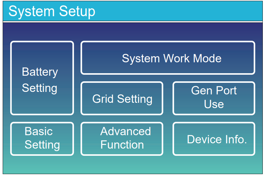
The System Setup screen provides access to the inverter’s configuration menus. Use Battery Setting for battery configuration, System Work Mode for operating priorities and schedules, and Gen Port Use for the GEN port’s function.
2. Shared battery settings — off-grid and on-grid
Battery Setting → Batt Mode
For the DEYE and RUIXU battery setups covered here:
- Select Lithium under Batt Mode for BMS communication.
- Tick Activate Battery.
- Enter the total battery-bank capacity in Ah.
- Enter the system’s Max A Charge and Max A Discharge limits.
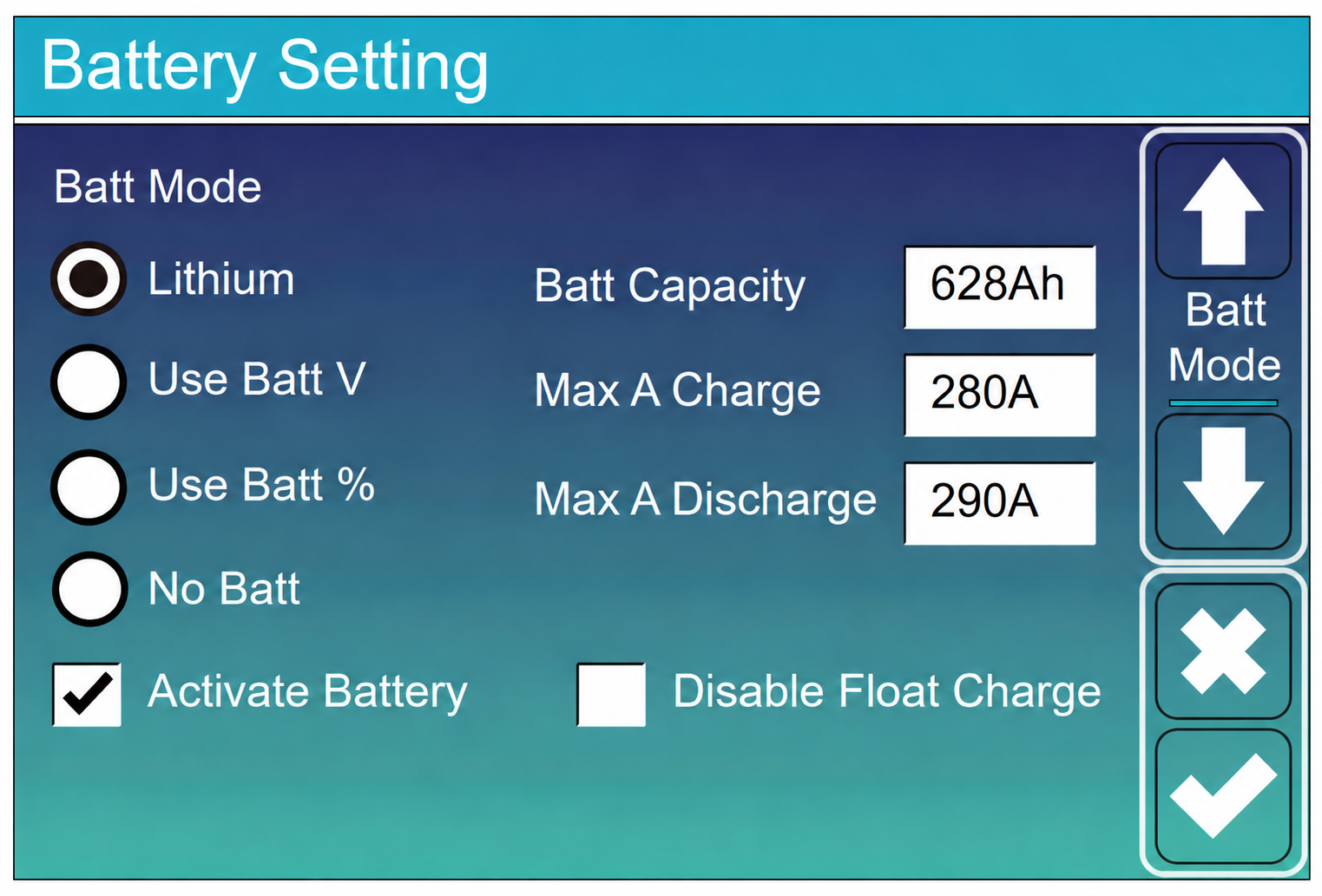
Activate Battery enables Deye’s slow recovery-charging function for an over-discharged battery. Lithium selects the battery mode used with BMS communication.
Total battery capacity
RUIXU Lithi2-16 batteries have a nominal capacity of 314 Ah each. For identical batteries connected in parallel, add their Ah capacities:
| Batteries in parallel | Batt Capacity |
|---|---|
| 1 × 314 Ah | 314 Ah |
| 2 × 314 Ah | 628 Ah |
| 3 × 314 Ah | 942 Ah |
For DEYE batteries, enter the combined Ah capacity of the installed parallel battery modules. Use the capacity stated for the particular battery model.
Typical wiring — three RUIXU batteries
Three RUIXU Lithi2-16 batteries connected in parallel provide a total capacity of 942 Ah. Each battery connects through its own DC branch MCCB to the common battery busbar. A separate dual-pole DC MCCB protects the connection between the combined battery bank and the inverter.
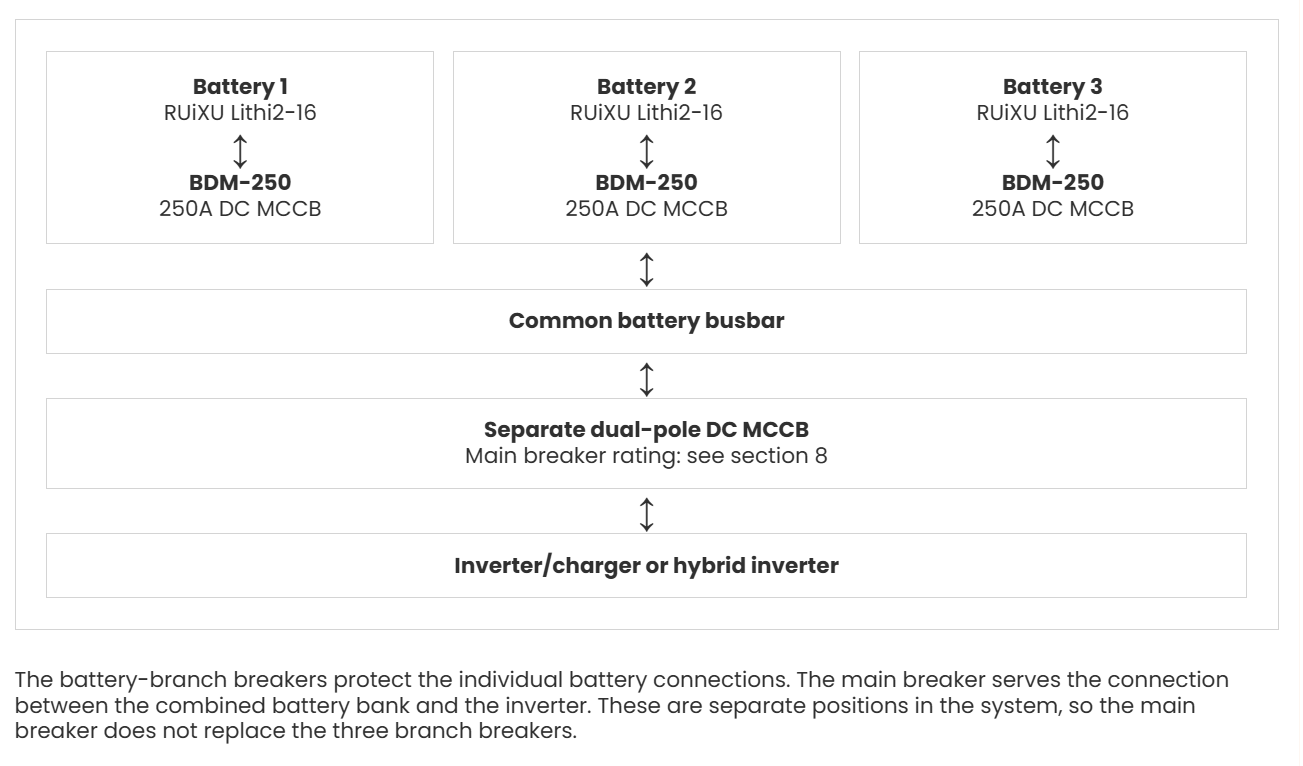
The branch breakers protect the individual battery connections; the main breaker protects the combined bank-to-inverter connection. Select the MCCBs and cabling for the connection using the ratings and AS/NZS requirements in Section 8.
RUIXU charging and discharging settings — one, two or three batteries
RUIXU recommends 140 A charge current per Lithi2-16 battery. For discharge, RUIXU recommends 140 A per battery and specifies 200 A maximum continuous discharge current per battery. Apply the inverter maximum to each combined battery-bank setting.
| RUIXU batteries | Batt Capacity | 10 kW DEYE 220 A maximum | 12 kW DEYE 250 A maximum | 16 kW DEYE 290 A maximum |
|---|---|---|---|---|
| 1 battery | 314 Ah | Charge: 140 A Discharge: 200 A | Charge: 140 A Discharge: 200 A | Charge: 140 A Discharge: 200 A |
| 2 batteries | 628 Ah | Charge: 220 A Discharge: 220 A | Charge: 250 A Discharge: 250 A | Charge: 280 A Discharge: 290 A |
| 3 batteries | 942 Ah | Charge: 220 A Discharge: 220 A | Charge: 250 A Discharge: 250 A | Charge: 290 A Discharge: 290 A |
The 10 kW and 12 kW columns apply to SUN-10K-SG02LP1-AU-AM3 and SUN-12K-SG02LP1-AU-AM3; the 16 kW column applies to SUN-16K-SG01LP1-AU-AM3. The SUN-12K-SG01LP1-AU-AM3 has a 220 A limit: use 140 A charge and 200 A discharge for one battery, and 220 A for both settings with two or three batteries.
For the 628 Ah bank illustrated above, Max A Charge is 280 A and Max A Discharge is 290 A, within the 16 kW inverter’s respective limits.
Deye SG02 10/12 kW specifications · Deye SG01 12/14/16 kW specifications
Reduce these current settings wherever required by the BMS, cables, busbars, connectors or circuit protection. The BMS also applies temperature-dependent limits.
RUIXU Lithi2-16 specifications and Australian documentation · RUIXU Australian datasheet · Deye Battery Setup
For cable sizing, busbar ratings and DC protection, see Section 8 — Battery MCCBs, cables and AS/NZS requirements.
Battery Setting → Batt Set3 — BMS and SOC control
The Deye setup shown below uses the following communications and state-of-charge settings. SOC means state of charge.
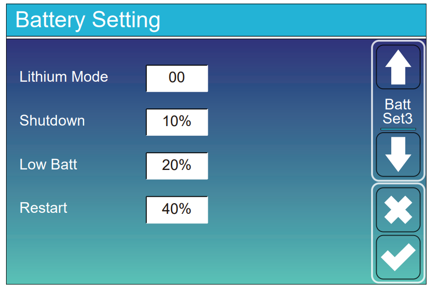
| Setting | Value shown | Function |
|---|---|---|
| Lithium Mode | 00 | BMS communications protocol shown in the Deye setup. |
| Shutdown | 10% | Low-SOC threshold below which the inverter shuts down. |
| Low Batt | 20% | Low-battery alarm threshold. |
| Restart | 40% | SOC required to resume AC output after a low-SOC shutdown. |
Use the battery manufacturer’s specified communications lead and BMS protocol. The SOC controls above apply to both the off-grid and on-grid sections of this guide.
OFF-GRID
3. Off-grid settings
For an installation with no connection to the electricity distribution network, complete the shared battery setup above and leave DRM off in Advanced Function.
| Menu | Off-grid setting or function |
|---|---|
| Battery Setting | Lithium mode, Activate Battery ticked, total bank capacity and system current limits. |
| Batt Set3 | Shared BMS/SOC setup: the Deye screen shows 00, 10% Shutdown, 20% Low Batt and 40% Restart. |
| Advanced Function → DRM | Off — unticked. |
| GEN port | Select Generator Input when a generator is connected to the GEN input. |
| Generator charging | Configure Gen Charge, the battery charging current and compatible remote-start controls for the generator installation. |
Battery Setting → Batt Set2 — generator charging
These controls configure charging from a generator connected to the inverter’s GEN input. Automatic starting uses a compatible generator controller connected to the inverter’s volt-free start contact.
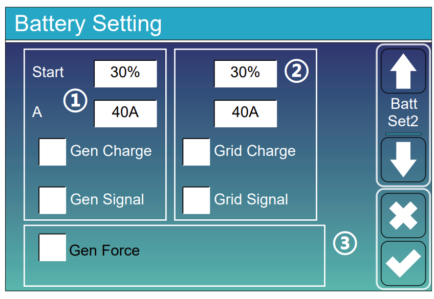
| Generator control | Meaning in the example |
|---|---|
| Start — 30% | Requests generator startup when battery SOC reaches 30%. |
| A — 40 A | Sets battery-side charging current from the generator to 40 A. |
| Gen Charge | Enables battery charging from the generator through the GEN input. |
| Gen Signal | Enables the start signal. The normally open relay contact closes when generator startup is requested. |
| Gen Force | Requests generator startup without waiting for the normal automatic-start conditions. |
The example’s 30% generator-start request occurs before the 20% Low Batt alarm and 10% Shutdown threshold. Set the charging current to suit the battery system and generator capacity, allowing for loads supplied while charging.
For scheduled generator charging, use the Gen column in Time of Use. The GEN Port Use section explains generator input power and the alternative port functions.
ON-GRID
4. On-grid settings
Complete the shared battery setup, then configure the operating mode, export controls, charging schedule and network communications for the connection.
| Menu | On-grid setting or function |
|---|---|
| Battery Setting / Batt Set3 | Use the shared battery, capacity, current and BMS/SOC setup. |
| System Work Mode | Select the mode for the connected loads and the required export behaviour. |
| Solar Sell | Leave unticked for zero-export operation; enable for an approved export configuration. |
| Time of Use | Set the charging sources, discharge-power limit and Target SOC for each period. |
| Grid Setting | Use the regional grid profile and parameters specified for the network connection. |
| DRM / network communications | Configure the wired GSD/DRED or approved communications arrangement required by the DNSP. |
System Work Mode → Work Mode1
This screen controls which circuits the inverter supplies, solar-energy priority and interaction with the grid.
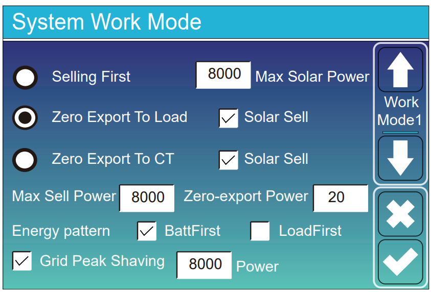
| Work mode | Operation |
|---|---|
| Zero Export To Load | Supplies circuits connected to the LOAD/backup output and charges the battery. With Solar Sell disabled, it does not supply grid-side household circuits or export. |
| Zero Export To CT | Supplies backup circuits and grid-side household loads. An external CT or supported meter measures grid flow for export control. Grid power supplements solar and battery power when needed. |
| Selling First | Allows surplus generation to feed into the grid. Battery export can also occur when configured through Time of Use. |
Solar Sell enables surplus solar export in either zero-export mode. Leave it unticked for zero-export operation. Set export controls to the connection’s approved limits.
Energy Pattern — solar priority
- BattFirst: solar energy prioritises battery charging, followed by supplying loads.
- LoadFirst: solar energy prioritises loads, followed by battery charging.
Work Mode1 power controls
| Setting | Function |
|---|---|
| Max Solar Power | Sets the permitted maximum DC solar-input power. |
| Max Sell Power | Sets the soft generation limit in Selling First, or the soft export limit in Zero Export To CT. |
| Zero-export Power | For zero-export operation, Deye recommends 20–100 W to help prevent unwanted feed-in. |
| Grid Peak Shaving | Uses solar and battery power to reduce grid demand towards the entered target. The grid can supply more when solar and battery power cannot cover the load. |
Deye System Work Mode manual, §5.7.
System Work Mode → Work Mode2 — Time of Use
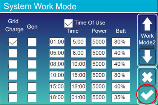
Tick Time Of Use to activate the schedule. Each row controls charging and battery discharge during a specified period.
| Setting | Function |
|---|---|
| Grid Charge | Enables grid charging during that period. |
| Gen | Enables charging from an attached generator during that period. |
| Time | Sets start and finish times using the 24-hour clock. |
| Power | Maximum permitted battery discharge power in watts. |
| Batt — Target SOC | The SOC target for the period. With Grid Charge or Gen enabled, charging is permitted towards the target. During normal on-grid battery use, discharge is permitted only above the target. |
Target SOC — how to read the on-grid example
Target SOC is the value entered in the inverter’s Batt column for each Time of Use period. With TOU enabled and grid power available, it controls charging towards that level and battery use above it.
Grid Charge ticked: if actual SOC is below Target SOC, the grid may charge the battery up to the target using the enabled grid-charging settings. If actual SOC is above Target SOC, the battery may supply loads down to that target.
Grid Charge unticked: the row does not request grid charging. The battery may supply loads only while actual SOC is above Target SOC. Solar charging remains available. The Gen tick separately permits scheduled generator charging.
| Period | Target SOC | Grid Charge | What this row permits |
|---|---|---|---|
| 01:00–05:00 | 80% | Ticked | Below 80%, grid charging may raise SOC to the target. Above 80%, the battery may supply loads down to the target. |
| 05:00–08:00 | 40% | Unticked | The battery may supply loads above 40%, down to the target. No grid charging is requested. |
| 08:00–10:00 | 40% | Unticked | The battery may supply loads above 40%, down to the target. No grid charging is requested. |
| 10:00–15:00 | 80% | Unticked | The battery may supply loads above 80%, down to the target. Below 80%, this row does not request grid charging. |
| 15:00–18:00 | 40% | Unticked | The battery may supply loads above 40%, down to the target. No grid charging is requested. |
| 18:00–01:00 the next day | 35% | Unticked | The battery may supply loads above 35%, down to the target. No grid charging is requested. |
Example — Target SOC 80%, actual SOC 60%: with Grid Charge ticked, scheduled grid charging may raise SOC towards 80%. Unticked, the row does not request grid charging and does not permit further normal on-grid battery discharge below the 80% target; solar can still replenish the battery. In Selling First mode, Time of Use can also allow battery energy to be exported.
For grid charging, also tick Grid Charge on Battery Setting → Batt Set2 and set the right-hand A field for battery charging current. The TOU Grid Charge tick selects the permitted periods. Deye marks the grid-side Start field as unused and Grid Signal as disabled in this menu.
5. Generator Port Use
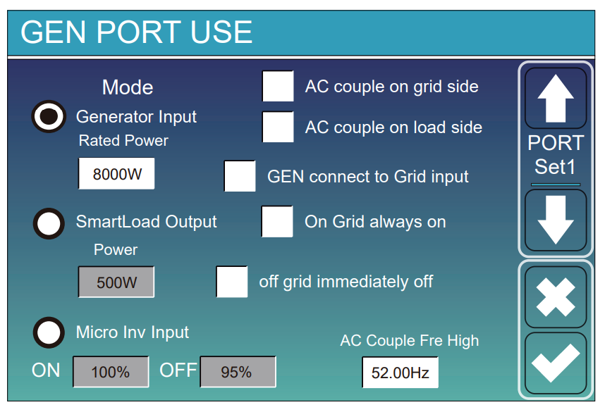
Choose the GEN port’s function in System Setup → Gen Port Use.
| Mode | Port function |
|---|---|
| Generator Input | Accepts AC power from a connected generator. |
| SmartLoad Output | Supplies a controlled load according to SOC and solar-generation thresholds. |
| Micro Inv Input | Accepts AC-coupled solar power from compatible microinverters or a grid-tied inverter. |
Generator Input
- Rated Power: maximum permitted generator input power, in watts.
- GEN connect to Grid input: identifies an installation where the generator connects through the inverter’s GRID input.
Generator rated input power and the battery charging-current setting are separate controls.
SmartLoad Output
In SmartLoad mode, the GEN port becomes a switched output. Power is the solar-generation threshold, ON is the battery SOC required to switch on, and OFF is the SOC below which the load switches off.
For Power = 500 W, ON = 100%, OFF = 95%, the load switches on when solar generation exceeds 500 W and SOC reaches 100%. It switches off when SOC falls below 95% or solar generation falls below 500 W.
- On Grid always on: keeps the smart-load output on while the grid is available.
- off grid immediately off: switches the smart-load output off when the grid disconnects.
Micro Inv Input and AC coupling
Micro Inv Input configures the GEN port as an input for a compatible AC-coupled solar inverter. In this mode, ON allows operation below the entered SOC threshold and OFF stops operation above its threshold.
AC Couple Fre High sets the high-frequency control point used to reduce or stop generation from a compatible coupled inverter as the battery approaches its OFF threshold.
AC couple on load side identifies solar connected through the LOAD output; Deye states that this arrangement affects displayed load-power accuracy. AC couple on grid side is marked reserved. Micro-inverter ON/OFF controls and other AC-coupling functions depend on firmware support.
6. Advanced Function — DRM
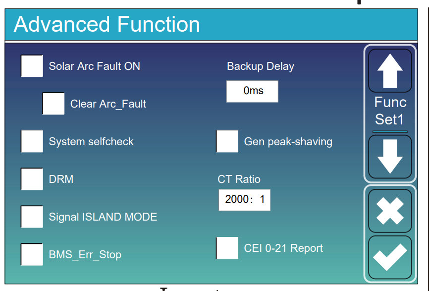
Off-grid installations: leave DRM switched off (unticked).
DRM means Demand Response Mode. The SUN-16K-SG01LP1-AU-AM3 supports DRM0 through its demand-response interface. An external demand-response enabling device (DRED) can use this interface to command the inverter to disconnect from the electricity grid. This is one method used for emergency solar backstop control. Deye manual, Advanced Function.
For an on-grid installation using a wired GSD/DRED, enable DRM and commission the connected device according to the network and inverter instructions. Where the network uses CSIP-AUS, configure the approved communications client or gateway and register it with the required utility server. The DRM checkbox and the CSIP-AUS communications setup perform different functions.
What hardware is required?
- Wired GSD/DRED arrangement: an approved device or controller, any auxiliary supply and protection required by its installation guide, and a control connection to the inverter’s demand-response interface. Multi-inverter sites can use individual devices or an approved demand-response site controller. Queensland’s GSD receives signals through the electricity supply using Audio Frequency Load Control (AFLC). Approved GSDs; Queensland installation and commissioning guide.
- CSIP-AUS arrangement: an approved inverter with the required communications software, or an approved external gateway, with registration and capability testing. Dynamic export services require ongoing communications; fixed-export alternatives have network-specific connectivity conditions. Use the equipment combination accepted by the relevant DNSP. Energex dynamic connections.
Australian DNSP requirements — expand for network, size and hardware references
A DNSP is the electricity distribution network serving the property. Select the network shown on the electricity bill or connection approval. The entries below describe requirements and announced rollouts at 30 October 2026.
Use the capacity measure stated by the network: inverter AC kVA and solar-panel DC kW are different ratings. Emergency backstop, flexible export control and interface protection have separate requirements.
Queensland — Energex and Ergon Energy Network
Trigger: applicable low-voltage connections with 10 kVA or more total inverter nameplate capacity at the premises, for connection offers accepted or contracts entered into from 6 February 2023. This covers new systems, capacity increases and relevant non-warranty replacements, including PV/battery hybrids and zero-export connections. Battery-only inverter capacity counts towards the site total, although a separate inverter supplied exclusively by battery storage is exempt from backstop control. The network’s table identifies affected existing inverters and warranty/non-NEM exclusions.
Equipment: an approved GSD and commissioned DRM0 connection where AFLC is available, or an approved CSIP-AUS dynamic connection. Where AFLC is unavailable, the network requires the CSIP-AUS route. A three-phase installation uses its total site inverter capacity for this test.
Energex requirements and applicability table · Ergon Energy Network requirements
New South Wales — Ausgrid
Announced rollout: registration for new or upgraded systems up to 200 kW starts 23 November 2026. Postcode-based backstop testing starts 30 November 2026, with all areas included by 22 February 2027.
Equipment: supported CSIP-AUS inverter/client or gateway, internet connection, registration and a successful capability test. Ausgrid specifies a 1.5 kW static export limit where internet connectivity is unavailable. Check the postcode rollout date and the connection approval’s commissioning deadline.
Ausgrid backstop rollout and requirements
New South Wales — Endeavour Energy
Announced rollout: registration and postcode-based implementation for new or upgraded systems up to 200 kW start 2 November 2026; all new or upgraded systems are to be backstop-enabled from 1 February 2027.
Equipment: supported CSIP-AUS equipment, internet connection, portal registration and capability testing. Endeavour specifies a 1.5 kW static export limit where internet connectivity is unavailable. Its connection approval sets the applicable commissioning deadline.
Endeavour Energy backstop rollout · Installer requirements
New South Wales — Essential Energy
Announced rollout: portal registration and postcode-based implementation start 2 November 2026 for new or upgraded systems up to 200 kW, progressing into early February 2027.
Equipment: a supported CSIP-AUS equipment combination onboarded to Essential Energy’s utility server, internet connection, registration and capability testing. Use the local rollout date and static export setting specified in the connection offer.
Essential Energy rollout, equipment and installer information
NSW’s program covers solar and PV/battery hybrid systems. An AC-coupled battery-only addition is treated separately. Existing unchanged systems and like-for-like warranty replacements have exemptions. Systems above 200 kW use the relevant network’s larger-system process. NSW Government scope and exemptions.
Victoria — AusNet, CitiPower, Powercor, Jemena and United Energy
Trigger: the small-system emergency backstop began 1 October 2024 for new, upgraded and relevant replacement rooftop solar. Each network publishes its capacity scope and application/replacement rules:
- AusNet: solar systems up to 200 kW, including relevant installations, upgrades, repairs and replacements. Applications approved before 1 October 2024 are exempt.
- CitiPower: rooftop PV systems up to 200 kVA; approved CSIP-AUS equipment, reliable internet and capability testing.
- Powercor: rooftop PV systems up to 200 kVA; approved CSIP-AUS equipment, reliable internet and capability testing.
- Jemena: rooftop PV systems up to 200 kVA; Jemena-approved CSIP-AUS inverter/equipment, internet connection and commissioning.
- United Energy: solar systems up to 200 kVA; CSIP-AUS commissioning to its utility server through an accepted inverter/client, gateway or aggregator arrangement. Its connection standard specifies internet and approved fallback arrangements.
Equipment: use the particular DNSP’s approved equipment combination and server registration process. PV-connected hybrid inverters are included; battery-only inverters have separate treatment. The statewide larger-system stage began 25 October 2023. Victorian Government backstop overview.
South Australia — SA Power Networks
Remote disconnection: new prescribed generation and specified replacements require an appointed, registered Relevant Agent under rules effective from 28 September 2020. The state rules include inverter-based energy storage; permanently zero-export plant has a specific exemption.
Equipment: a Relevant Agent-supported remote-control solution, such as inverter communications, an internet-connected control device or an approved switching arrangement. The agent’s accepted technology determines the hardware.
Dynamic exports: from 1 July 2023, new exporting generation must have certified dynamic-export capability unless exempt. Flexible Exports uses supported CSIP-AUS equipment, internet and commissioning. The fixed-export option does not require the dynamic-export capability test; permanently zero-export systems are exempt. A battery-only addition to existing PV does not itself trigger dynamic-export capability; new PV with battery storage must meet the PV-side requirements.
SA remote-disconnect requirements · SA dynamic-export scope and exemptions · SA Power Networks Flexible Exports
Western Australia — Western Power / SWIS
Trigger: from 1 May 2026, new or upgraded SWIS solar/battery systems up to 30 kVA must support the required modern communications and pass remote disconnect/reconnect capability testing.
Equipment: Synergy customers use CSIP-AUS equipment and commissioning; other retailers may specify a different accepted solution. Export products require the retailer’s remote-management arrangement. After capability testing, customers opting out of export products or unable to maintain stable internet can use the standard 1.5 kW export limit under the published policy and connection conditions.
WA technical requirements · Installer and retailer requirements
Western Australia — Horizon Power
Trigger: Horizon’s low-voltage embedded-generation requirements specify energy management for all LV generation connections.
Equipment: Horizon’s provisioned Secure Gateway Device (SGD), the required enclosure and electrical/interface facilities, compatible inverter communications and the specified internet access. The system connects to Horizon’s Distributed Energy Resource Management System (DERMS). Its inverter settings specify DRM0 enabled and DRM1–8 disabled.
Horizon Power LV requirements — energy management and Appendix G
Australian Capital Territory — Evoenergy
Planned program: Evoenergy’s published planning report describes a 2026–2028 rollout, subject to the ACT regulatory framework and Technical Code.
Planned equipment and process: CSIP-AUS communications, installer registration and capability testing. For an installation’s current requirements, use Evoenergy’s connection offer and technical conditions.
Tasmania — TasNetworks
Connection requirements: the Basic Micro category covers up to 10 kVA per phase. Use the applicable Basic Micro or LV embedded-generation specification and the site’s approved export limit. The Basic Micro specification requires the installer to record enabled demand-response modes and their implementation in the as-built information.
Equipment: approved inverter settings and any export-control or additional control equipment specified in the connection offer. The network’s connection requirements determine the equipment for the installation.
TasNetworks embedded-generation requirements · Basic Micro specification
Northern Territory — Power and Water
Basic Micro connections: the published specification covers eligible urban systems up to 10 kVA single-phase or 30 kVA three-phase. It specifies no communications system for solar-only installations; systems containing battery storage require internet/VPP-capable communications, remote registration and battery charge/discharge control capability.
Larger or negotiated connections: where Power and Water requires dynamic export control, it supplies the local controller and communications arrangement. The connection agreement specifies the operating limits and control requirements. Remote and minor networks use their own connection conditions.
Power and Water also reports using Solar Backstop technology to prevent solar exports during power-system risk events. Network planning report, Solar Backstop and Flexible Exports.
Power and Water connection classes · Basic Micro specification, §4.11 · Negotiated specification, §§4.3.1 and 4.11
7. Deye setup video
Deye New Energy’s Hybrid Inverter Quick Setup Guide Video demonstrates the settings menus and operating modes.
Watch the full video on YouTube · System Work Mode example at 4:01
8. Battery MCCBs, cables and AS/NZS requirements
Use Deye’s battery-connection and protection recommendations in §3.4 and §3.12 of the inverter manual together with the battery manufacturer’s instructions.
Branch and main MCCBs
Rate each battery-branch MCCB for its battery connection and conductors. Rate the separate dual-pole DC main MCCB for the combined bank-to-inverter connection, coordinated with the inverter, cables, busbars and connectors. The main MCCB serves a different connection from the individual branch MCCBs.
Determine the continuous-current rating, DC voltage rating and fault-interrupting capacity for the installed connection. Cable selection needs to account for current-carrying capacity after temperature and installation derating, voltage drop over the complete circuit, and short-circuit withstand. Coordinate the protective devices with the conductors and equipment.
Australian/New Zealand installation references
- AS/NZS 3000:2018 — Wiring Rules: installation design, equipment selection and protection.
- AS/NZS 3008.1.1:2025 — Cable selection, Australian conditions: current-carrying capacity, correction factors, voltage drop and short-circuit temperature rise.
- AS/NZS 5139:2019 — Battery-system installation safety, including applicable amendments.
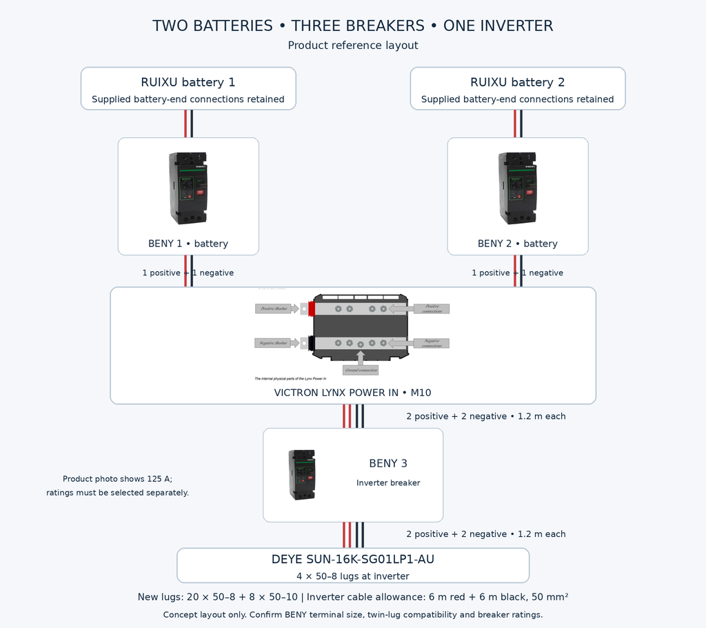
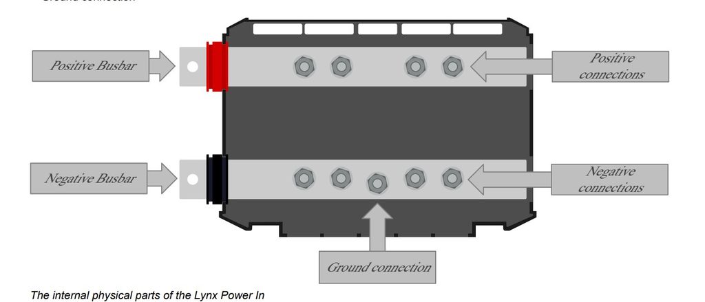
VIctron Power In – Busbar
CABLES AND BUSBAR, LUGS
Victron Lynx Power In — cable and lug requirements
The Lynx Power In uses M10 cable connections. The Deye inverter uses M8 connections. The quantities below assume the ZJ Beny breakers also accept M8 lugs; confirm the breaker terminals before ordering.
1. Two RUIXU batteries → battery breakers → Lynx busbar
Each battery has one positive and one negative cable. Cut the supplied 1.2 m cables at the breaker location, retaining the existing battery-end connections.
For each battery, fit:
- 4 × 50–8 lugs at the breaker: two incoming and two outgoing.
- 2 × 50–10 lugs at the Lynx busbar: one positive and one negative.
For two batteries, this requires 8 × 50–8 and 4 × 50–10 new lugs.
Cutting the supplied cables does not increase their length: each complete battery-to-busbar route remains approximately 1.2 m.
2. Lynx busbar → inverter breaker → Deye SUN‑16K‑SG01LP1‑AU
Use two 50 mm² positive cables and two 50 mm² negative cables throughout this section.
Allowing 1.2 m from the busbar to the breaker, plus 1.2 m from the breaker to the inverter:
| Cable | Measured requirement | Suggested allowance |
|---|---|---|
| Red 50 mm² copper | 4.8 m | 6 m |
| Black 50 mm² copper | 4.8 m | 6 m |
| Total | 9.6 m | 12 m |
The 12 m allowance is for the inverter section, with extra length for routing and termination.
| Connection | Lugs required |
|---|---|
| Lynx busbar | 4 × 50–10 |
| Beny breaker input | 4 × 50–8 |
| Beny breaker output | 4 × 50–8 |
| Deye inverter | 4 × 50–8 |
The breaker must accommodate the twin cable connections.
Total new lugs to order
| Section | 50–8 lugs | 50–10 lugs |
|---|---|---|
| Two batteries through their breakers to Lynx | 8 | 4 |
| Lynx through inverter breaker to Deye | 12 | 4 |
| Total | 20 | 8 |
Order: 20 × 50–8 lugs, 8 × 50–10 lugs, 6 m red cable and 6 m black cable.
This retains the four existing battery-end connections. If those also need replacing with M8 lugs, add 4 × 50–8, bringing that quantity to 24.