
How to charge an LFP battery for longer life
LiFePO4 cells are tough, but charging conditions still matter. Cold cells, unnecessary current and long periods near full charge can all add stress over time.
Our approach is straightforward: stay within the exact manufacturer limits, reduce charge current when conditions are less favourable, and let the BMS communicate those limits directly to the charging system.
The cell manufacturer's specification comes first. Our long-life settings sit below it on purpose, and the lowest applicable limit always wins.
This guide shows the settings, explains why they matter and covers practical implementation with Victron DVCC, Deye and other compatible charging systems.
Important: Manufacturer data is revision-specific. Always use the exact specification supplied for your cell. Do not copy settings from another cell model or revision.
What matters most
The exact cell datasheet and completed-battery limits set the ceiling. Never copy settings from a different cell or revision.
3.45V, 3.50V and 3.55V per cell can all be valid profiles when approved for the battery. Do not use 3.65V/cell as a routine target.
For occasional cold trips, follow the exact cell and BMS limits. For repeated charging at or below 12°C, our long-life profile requires controlled battery heating.
A communicating BMS should send charge-current and charge-voltage limits to the inverter. Whichever active limit is lowest wins.
Start with the basic principle: a maximum is not a target
Cell specifications usually contain several different kinds of numbers:
- a standard charge rate used for testing;
- a maximum continuous charge rate;
- a short pulse or regenerative limit;
- an absolute voltage or temperature boundary;
- and, in some documents, a table that changes the limit with SOC, temperature, voltage or state of health.
These figures answer different questions. An absolute boundary tells the BMS where operation must stop. A standard test rate describes the manufacturer's test. A dynamic table tells the system designer how much current or power may be accepted under a specific condition.
LiFePO4 Australia's long-life curve sits below those limits. It does not increase a cell's rating, and it does not replace any battery-level limitation. If a completed battery, contactor, fuse, busbar, BMS or inverter is rated below the cell ceiling, the lower system value remains decisive.
What the cell manufacturers publish
The chart keeps C-rate cells separate from the EVE MB31, which is specified in P-rate. That distinction matters: 0.5P is a power limit, while 0.5C is a current limit based on capacity.
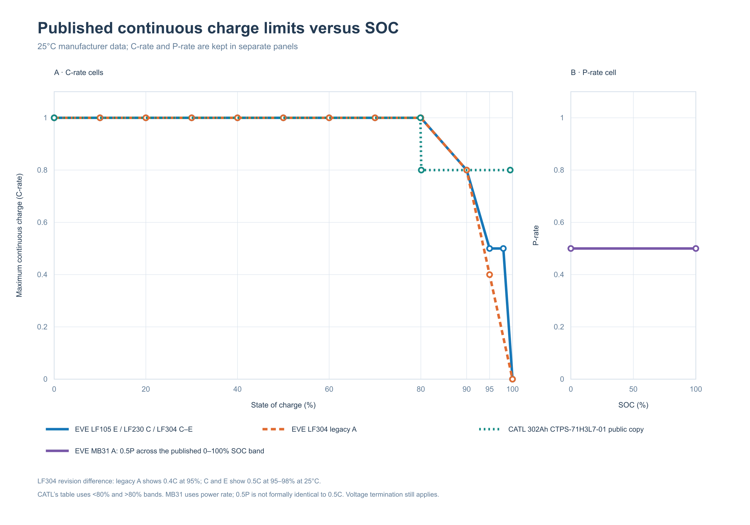
Figure 1. Manufacturer-published continuous charge limits at 25°C. C-rate and P-rate are shown in separate panels. Lines connect published points or bands; they are not LiFePO4 Australia recommendations.
Several EVE power-cell specifications show the same high-SOC pattern at 25°C:
- EVE LF105 Version E: 1C through 80% SOC, 0.8C at 90%, 0.5C at 95–98%, and 0 at 100%.
- EVE LF230 Version C: the same 1C → 0.8C → 0.5C pattern at 25°C.
- EVE LF304 Versions C and E: the same pattern at 25°C.
- EVE LF304 legacy Version A: 1C through 80%, 0.8C at 90% and 0.4C at 95%.
The LF304 revision difference is important. The broad principle remains stable, but the exact high-SOC value changed between the public Version A copy and later Versions C/E. This is why a warranty or control schedule must name the cell model, specification number and revision.
CATL independently publishes an SOC-dependent limit for its 302Ah cell. In the public copy of specification CTPS-71H3L7-01, the 25°C limit is 1C below the 80% SOC band and 0.8C above it. The table is less granular than EVE's but demonstrates the same principle: the allowable maximum can change with SOC.
The EVE MB31 Version A specification uses a different strategy. It publishes 0.5P across the 0–100% SOC band at normal cell temperatures rather than the LF304-style high-SOC table. Our SOC taper is therefore an additional long-life recommendation for MB31, not an EVE requirement.
Why LF304 revision numbers matter
The LF304 model name alone is not enough. Different specification revisions publish different high-SOC limits:
- the May 2021
RD-LF304-S01-LFVersion A table shows 0.4C at 95% SOC at 25°C; - the April 2022
PBRC-LF304-S01-LFVersion C table shows 0.5C at 95% and 98%; - the May 2023
PBRI-LF304-D06-01Version E table retains 0.5C at 95–98% and adds much finer cold-temperature resolution, including SOC-dependent limits below 10°C.
For that reason, every LF304 value in this guide is tied to a named document revision. The temperature comparison uses the newer Version E table.
Why cold cells need less charge current
Low-temperature charging is not simply a slower version of warm charging. As the cell becomes cold, electrolyte conductivity, charge-transfer kinetics and lithium diffusion through the graphite electrode become less favourable. Polarisation rises, and the margin against metallic lithium deposition can reduce.
Manufacturers deal with this by derating charge current or power. But the precise curve depends on the cell.
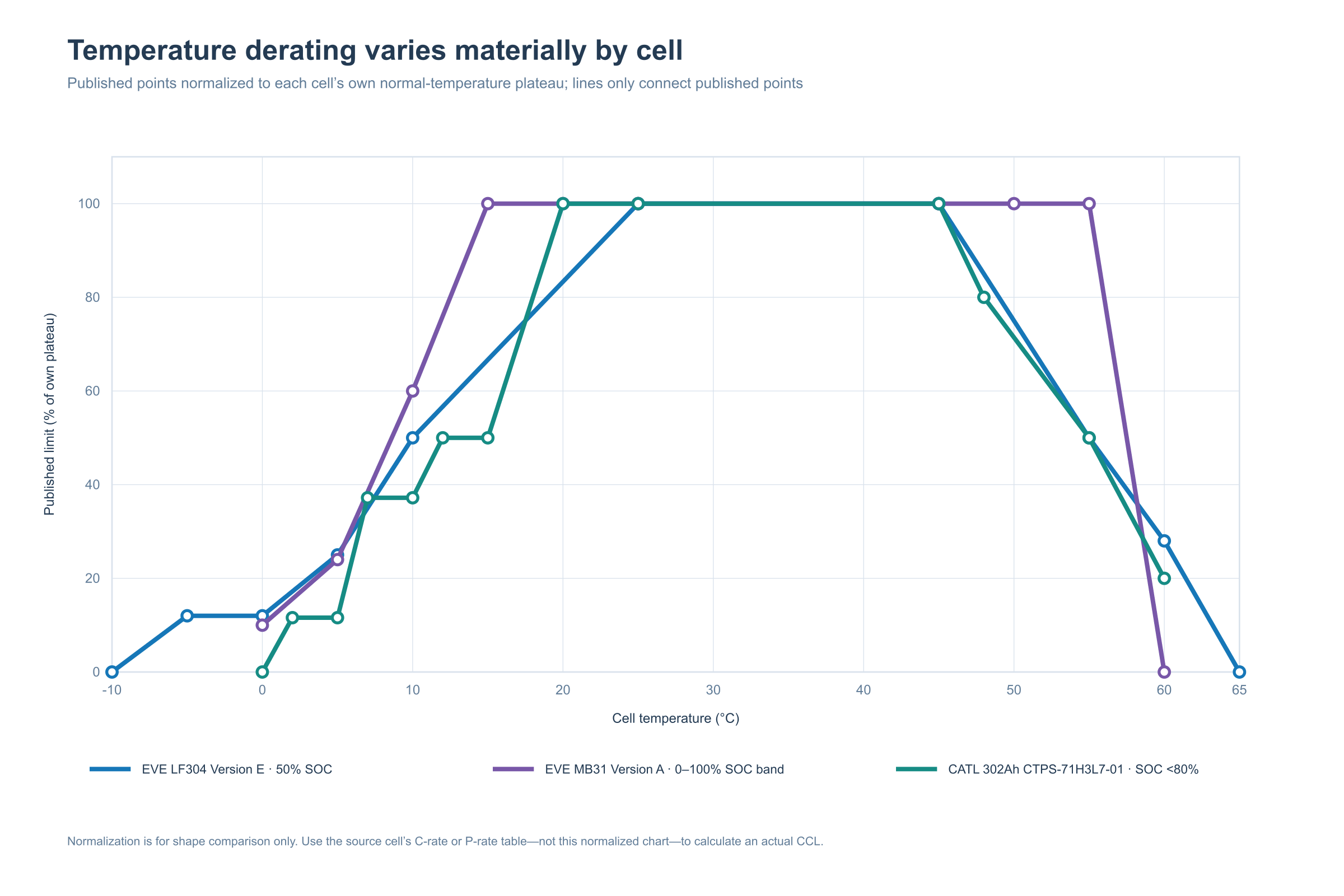
Figure 2. Three representative published temperature curves, normalized to each cell's own normal-temperature plateau so their shapes can be compared. The EVE LF304 Version E series is the 50% SOC slice; CATL is the below-80% SOC band; MB31 applies across its published 0–100% SOC band. Use the source table—not this normalized chart—to calculate an actual CCL.
The three examples make the point clearly:
- EVE LF304 Version E, 50% SOC: 0.12C at 0°C, 0.25C at 5°C, 0.5C at 10°C and 1C at 25–45°C. It derates again at high temperature.
- EVE MB31 Version A: 0.05P at 0°C, 0.12P at 5°C, 0.3P at 10°C and 0.5P from 15°C through 55°C, then 0 at 60°C.
- CATL 302Ah, below 80% SOC: 0 at 0°C, 0.116C at 2–5°C, 0.372C at 7–10°C, 0.5C at 12–15°C and 1C at 20–45°C, followed by hot-temperature derating.
These curves are different, so the exact cell specification must always come first. Our 12°C charging stop is a conservative option for batteries that repeatedly charge in cold conditions; it is not a claim that every EVE or CATL cell is prohibited from charging below 12°C. An occasional cold-weather trip does not automatically ruin a battery when the exact cell and BMS limits are followed.
Repeated cold charging deserves more attention than an isolated trip, especially as cell temperature approaches 0°C or charge current rises. There is no defensible universal rule that one cold charge equals “10 or 20 normal cycles,” so we do not assign an invented cycle penalty to it.
Reduce current as the battery fills
Our SOC curve begins reducing current gently above 70% and becomes progressively more conservative near full charge.
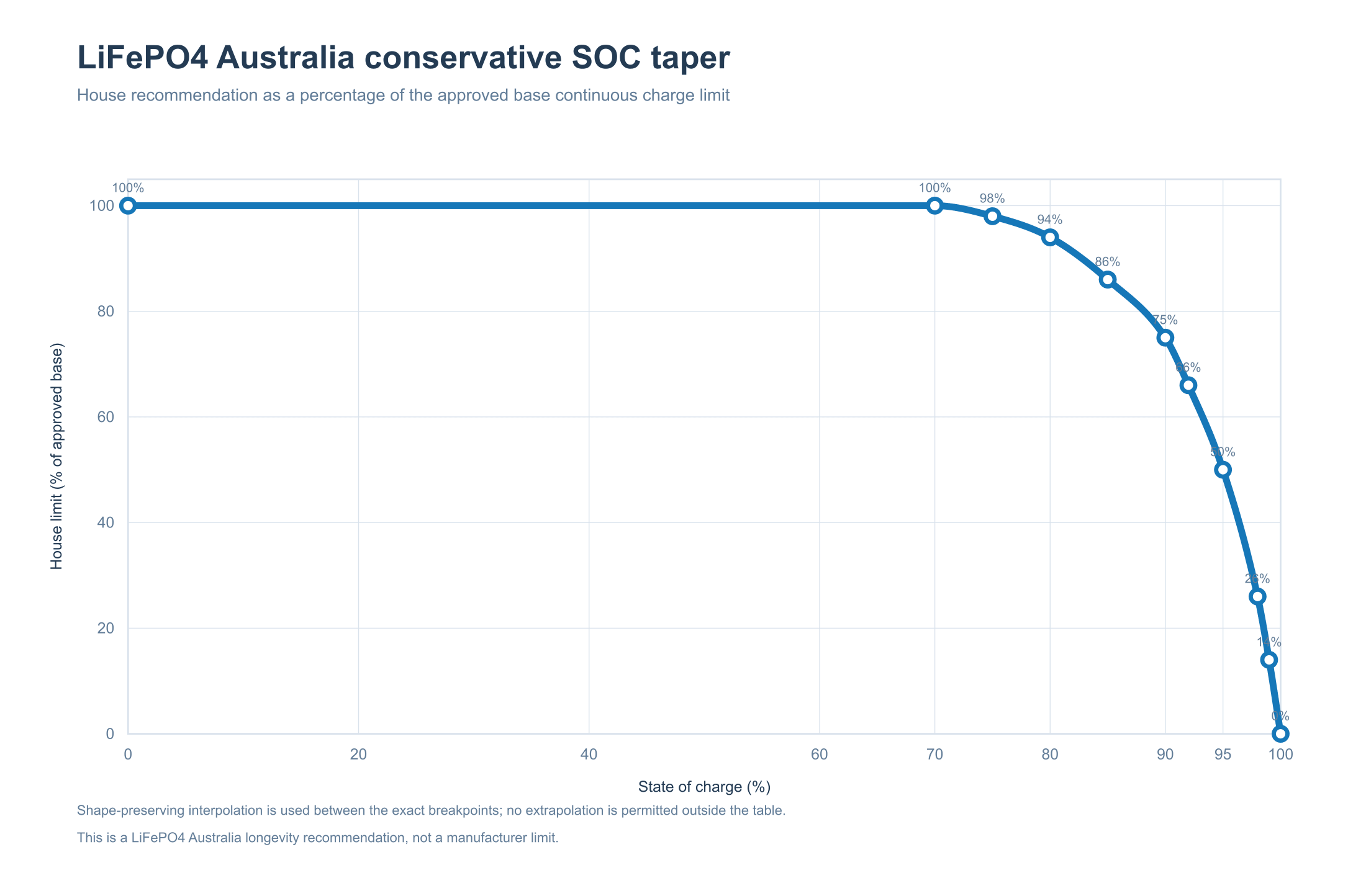
Figure 3. Our long-life recommendation. Percentages apply to the approved base continuous charge limit, not an arbitrary cell maximum.
| SOC | Our CCL ceiling |
|---|---|
| ≤70% | 100% of approved base |
| 75% | 98% |
| 80% | 94% |
| 85% | 86% |
| 90% | 75% |
| 92% | 66% |
| 95% | 50% |
| 98% | 26% |
| 99% | 14% |
| 100% | 0% |
The BMS should use straight-line interpolation between the listed breakpoints. The chart is smoothed for readability; the table contains the settings used for control.
This curve is intentionally labelled a recommended long-life profile, not an “ideal” or scientifically optimal curve. Published data supports the direction of the taper, but it does not prove that 66% rather than 65% at 92% SOC is universally optimal for every LFP cell.
Cold battery? Slow down—or heat it
The temperature curve is governed by the coldest valid cell sensor while charging. It is an optional precautionary profile intended mainly for repetitive or daily cold-weather operation. It is not a universal boundary between safe and unsafe charging.
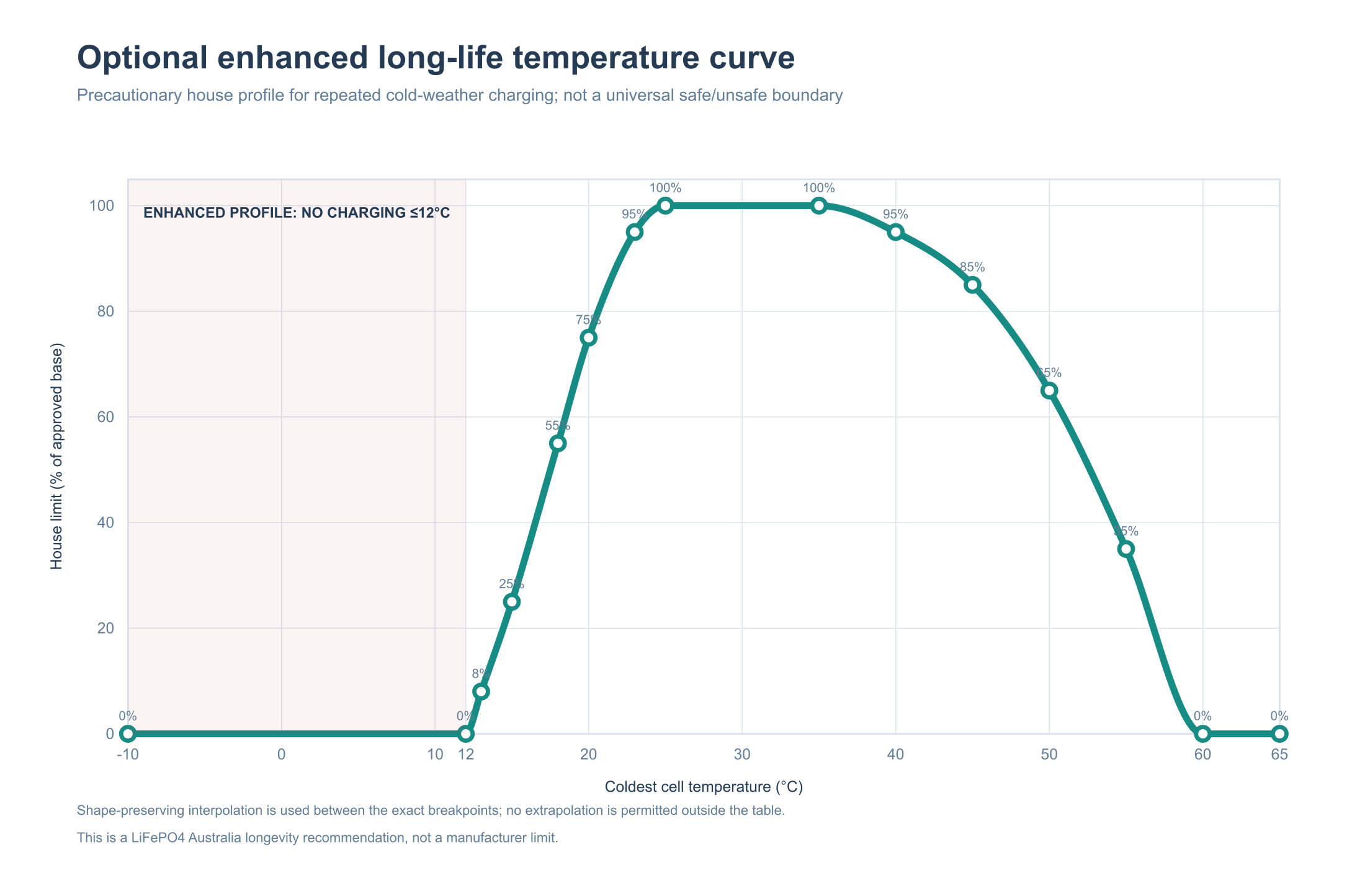
Figure 4. Optional LiFePO4 Australia enhanced long-life profile. Within this profile, charging is disabled at or below 12°C and recovers gradually as the cells warm. Manufacturer-permitted occasional cold operation is addressed separately below.
| Coldest cell temperature | Our CCL ceiling |
|---|---|
| ≤12°C | 0% — no charging |
| 13°C | 8% |
| 15°C | 25% |
| 18°C | 55% |
| 20°C | 75% |
| 23°C | 95% |
| 25–35°C | 100% |
| 40°C | 95% |
| 45°C | 85% |
| 50°C | 65% |
| 55°C | 35% |
| ≥60°C | 0% — no charging |
Occasional cold-weather use
A few days of winter camping is different from charging a stationary battery at low temperature every morning for months. If the exact cell revision permits charging at the measured temperature, the BMS applies the correct temperature-and-SOC limit, all sensors are valid and the charger obeys the CCL, occasional operation below the enhanced-profile range is not automatically prohibited by this guide.
Near 0°C, however, several cited cell tables allow either no charging or only very low current. There must not be a generic “all LFP cells can charge at 0°C” setting. The exact cell specification remains decisive, and the coldest cell—not outdoor air or an enclosure average—governs.
When heating becomes important
If cells are expected to charge at or below 12°C repeatedly or daily—for example through a cold Tasmanian winter or in another cold-climate stationary installation—a suitable heater becomes a practical requirement for compliance with the enhanced long-life profile. A heater is not automatically mandatory merely because an otherwise warm installation may experience an isolated cold trip, provided the system follows the exact manufacturer/BMS limits during that event.
The heater must:
- be controlled from actual battery/cell temperature, not outdoor air temperature alone;
- include appropriate electrical protection and independent over-temperature protection;
- heat the pack evenly enough to avoid a warm sensor masking a cold cell;
- be interlocked so enhanced-profile charging remains disabled until every governing sensor is at least 13°C for five minutes;
- and be installed so that local hot spots cannot damage cells, insulation, wiring or the enclosure.
Charging current must not be used as the primary method of warming a cold cell.
One rule: use the lowest limit
Your battery can have several charge limits at the same time. One may come from temperature, another from SOC and another from the highest cell voltage. Compare them and use whichever one allows the least charging current. Do not multiply the percentages together.
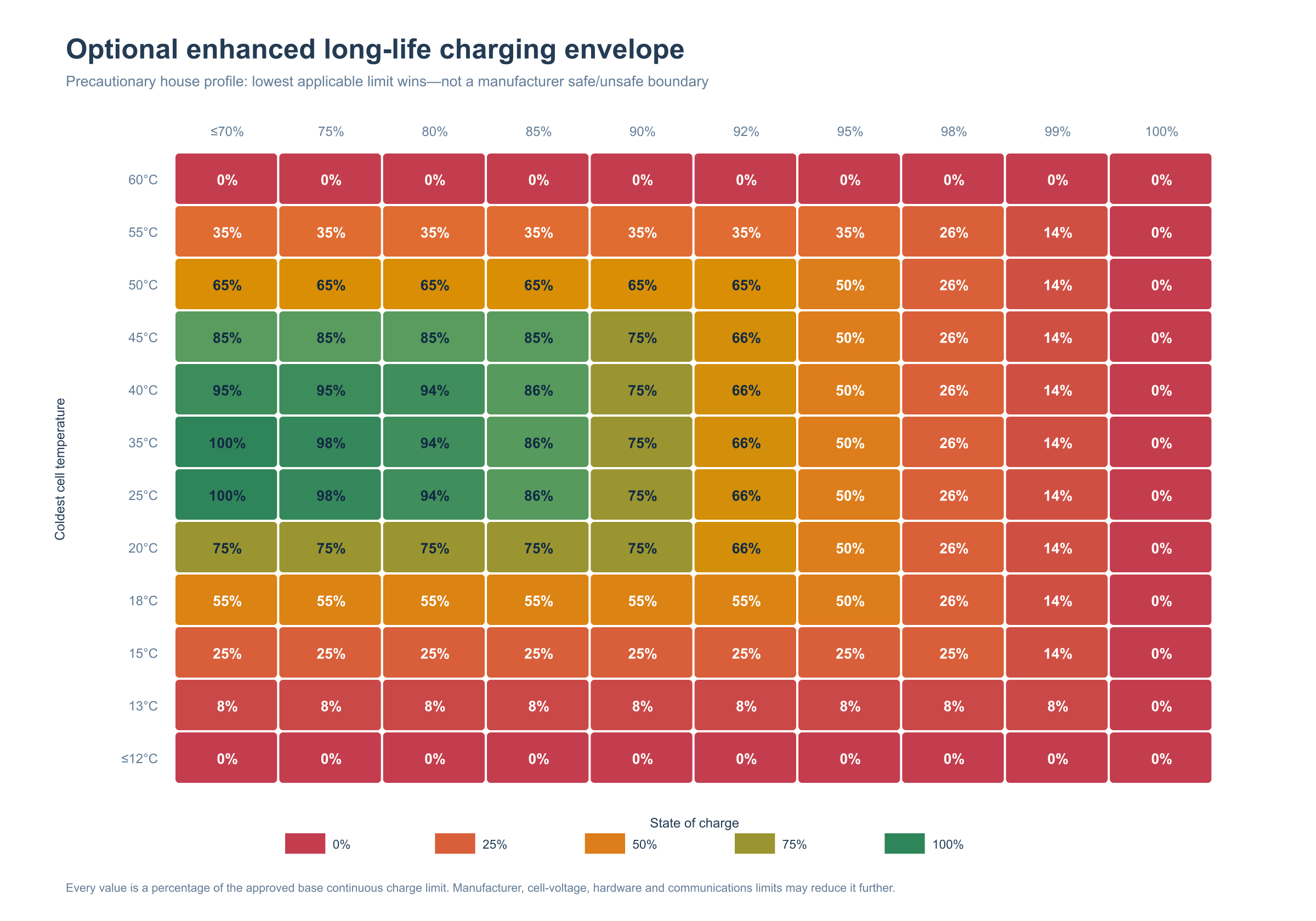
Figure 5. Combined long-life envelope. Each cell is a percentage of the approved base continuous charge limit. Manufacturer, voltage, hardware and system limits may reduce it further.
At 20°C and 90% SOC, both curves allow 75%, so the result is 75%, not 56.25%.
At 15°C and 95% SOC, temperature allows 25% while SOC allows 50%, so 25% wins.
Then compare that result with every other limit in the system:
- the approved base limit for the completed battery;
- the manufacturer's SOC, temperature, voltage and state-of-health limits;
- the highest-cell-voltage and cell-imbalance limits;
- the ratings of the BMS, contactors, busbars, fuses and cables; and
- the inverter, charger and site limits.
Turn the limit into charging amps
For a C-rate cell, multiply the permitted C-rate by the capacity basis required in the cell specification. Do not assume that nameplate capacity is always the correct figure; CATL's public 302Ah specification, for example, defines charge rate against capacity measured by the BMS.
For a P-rate cell such as MB31, calculate in power first and convert at the measured pack voltage.
The EVE MB31 Version A document gives 1004.8Wh nominal cell energy and 502.4W for 0.5P at beginning of life. For a 16-series string:
Charge-current limit = 8,038.4W ÷ measured pack voltage
That is approximately 157A at 51.2V, but approximately 146A at 55.2V. Calling both “0.5C = 157A” would lose the distinction EVE deliberately made by specifying P-rate.
Choose the right charge voltage
Dynamic current control works best when the BMS also publishes an appropriate Charge Voltage Limit. There is no single universally correct LFP charge voltage: the correct profile is the one approved for the completed battery, BMS, charger and intended duty.
LiFePO4 Australia therefore treats 3.45V, 3.50V and 3.55V per cell as three legitimate selectable profiles when they are approved for the battery. They should not be coloured or described as a progression from “good” to “bad”:
- 3.45V/cell is a gentle daily option. It may reduce time at the upper knee, but it can also provide less balancing time or fail to trigger a poorly coordinated 100% SOC reset.
- 3.50V/cell is a normal approved option that provides more headroom for reaching full-charge conditions without using the upper datasheet ceiling.
- 3.55V/cell is a valid full-charge profile for batteries designed around it. Victron's current Lithium Battery Smart manual recommends 14.2V for a 12.8V battery—equivalent to 3.55V/cell—and specifies an allowable charge-voltage range of 14.0–14.4V, or 3.50–3.60V/cell, for that Victron battery family.
For Victron's own Lithium Battery Smart range, 3.55V/cell is a normal approved charging target. Other batteries may require different settings, so confirm the cell, BMS and completed-battery limits before using it elsewhere.
For a battery whose BMS declares 100% SOC from a per-cell voltage threshold, the settings should follow this order:
The routine charger target should be at least 0.01V per cell above the BMS's 100% SOC reset threshold, while remaining below the battery's approved charge-voltage ceiling and below the BMS cell-overvoltage threshold by a deliberate engineering margin. For a 16S battery, a 0.01V-per-cell difference is 0.16V at pack level. The required real margin may be larger when BMS and charger measurement accuracy, calibration, resolution, wiring drop or cell imbalance are considered.
If those conditions cannot all be satisfied, do not place the routine target close to overvoltage protection. Lower the SOC-reset threshold where the approved BMS permits it, or use another battery-specific commissioning value. The overvoltage trip is emergency protection, not a normal way to terminate charging.
| Per-cell target | 4S / nominal 12V | 8S / nominal 24V | 16S / nominal 48V | Intended interpretation |
|---|---|---|---|---|
| 3.40V | 13.60V | 27.20V | 54.40V | Very gentle/limited-voltage option; may not reliably reach the BMS's full-charge or SOC-reset conditions |
| 3.45V | 13.80V | 27.60V | 55.20V | Gentle approved profile |
| 3.50V | 14.00V | 28.00V | 56.00V | Normal approved profile |
| 3.55V | 14.20V | 28.40V | 56.80V | Full-charge approved profile; also Victron's recommended per-cell equivalent for its Lithium Battery Smart range |
| 3.65V | 14.60V | 29.20V | 58.40V | Common datasheet end-of-charge or ceiling value; not our routine target and not permissible if it equals/exceeds BMS OVP |
Balancing is governed by the BMS's configured balance-start voltage, cell-voltage difference, balancing current and available balancing time. Some LiFePO4 Australia systems balance effectively around 3.38–3.40V per cell. There is no universal requirement to use 3.50–3.55V solely to make balancing begin; however, 3.50V or 3.55V can still be the correct routine charge profile for a battery designed and commissioned around those values.
These are our recommended profiles, not universal manufacturer values. The exact cell and battery specification remains decisive. Many LFP documents use 3.65V as an end-of-charge or absolute ceiling; an absolute ceiling must not be mistaken for a routine charging target.
The BMS must reduce CVL or set CCL to zero if a high cell, imbalance, temperature or other condition requires it. Independent hardware high-voltage protection remains necessary even when CAN or RS485 communications are operating normally.
How to apply this with Victron DVCC
Victron's current GX documentation says that a managed CAN-bus battery sends Charge Voltage Limit, Charge Current Limit and Discharge Current Limit to the GX device, which relays them to supported inverter/chargers, solar chargers and Orion XS chargers through DVCC. Victron also states that when both a user-set system charge-current limit and BMS CCL exist, the lower value is used.
Set it up this way:
- Connect the approved BMS to the GX device using the correct BMS-Can/VE.Can interface, cable and termination.
- Enable DVCC and confirm that the intended battery is the controlling BMS and SOC source.
- Set the manual DVCC maximum no higher than the approved battery hardware/base limit.
- Verify that live CVL, CCL and DCL values update as the BMS test inputs change.
- Test all charge sources. Victron documents that unsupported or unconnected chargers and alternators may not be controlled or counted by DVCC.
- Test a controlled sequence such as 100A → 40A → 0A and confirm the actual battery current follows it.
Victron tail current is not dynamic current control. It is primarily part of charged-state/SOC synchronisation. Use BMS CCL through DVCC to throttle charge current.
How to apply this with Deye
Deye hybrid inverters support lithium-battery communications over CAN or RS485 on relevant models, and current product material describes lithium charging as self-adapting to the BMS. The exact protocol selection, menus and behaviour vary with inverter model and firmware, so compatibility must be verified rather than assumed.
Set it up this way:
- Select lithium mode and the exact protocol supported by both the BMS and the Deye model/firmware.
- Set the inverter's maximum charge current no higher than the approved battery hardware/base limit.
- Confirm on live screens that SOC, voltage, current, requested charge current, temperature and alarms are valid.
- Test that the inverter follows changing BMS current requests, including a 0A request.
- Test communications loss. Charging must stop or enter a formally validated safe fallback; the inverter must not silently continue with an uncontrolled lead-acid profile.
- Validate aggregation when batteries are paralleled. Do not simply multiply one pack's limit without checking the master BMS, busbars, fuses, contactors, pack balance and protocol behaviour.
The most reliable way to control charging
Compatible Victron and Deye systems can follow a changing charge-current limit from the battery BMS. The remaining job is to confirm that the exact BMS, inverter model, protocol and firmware combination exchanges the correct values and responds safely when communications fail.
| Method | What it does | Our recommendation |
|---|---|---|
| Managed BMS → Victron GX/DVCC | The BMS sends dynamic CVL, CCL and DCL values, and supported Victron chargers follow them. | Preferred Victron method |
| Managed BMS → Deye lithium CAN/RS485 | The BMS sends charge voltage, charge current, discharge current, SOC and temperature limits to the inverter. | Preferred Deye method after compatibility testing |
| Venus OS Large / Node-RED → Victron | Reads battery data and can apply supported controls through Venus OS. | Useful for monitoring, prototyping or a carefully engineered supervisory cap |
| Dedicated dual-CAN ESP32 gateway → Deye | Reads the original BMS frames and can reduce the charge limits before forwarding them to the inverter. | A possible fallback when the BMS cannot calculate the curve; requires fail-safe commercial engineering |
| Raspberry Pi protocol bridge | Reads BMS data and publishes inverter-compatible CAN/RS485 data. | Useful for development and monitoring, but not recommended as the only real-time protection controller |
The best arrangement is simple: the BMS calculates the safe current and sends it directly to the inverter. The BMS already knows the cell voltages, temperatures, SOC, fault state and contactor state, so it should remain in charge of battery protection.
If the existing BMS firmware cannot calculate the curve, the next-best approach is a dedicated, fail-safe microcontroller gateway—not a general-purpose computer as the sole control layer. It should have isolated communications, a hardware watchdog, protected power, deterministic startup and an independent charge-disable output. A Raspberry Pi or GX/Node-RED system remains valuable for configuration, monitoring, logging and alarm reporting.
Regardless of platform, an additional controller may only reduce the BMS limit:
Final CCL = the lowest of the BMS limit, manufacturer limit, our SOC limit, our temperature limit, cell-voltage limit, hardware limit and inverter limit.
An external controller must never increase the current above the value allowed by the real BMS. Missing or implausible temperature data, stale BMS data, controller failure or lost communications must result in 0A charging or a separately validated charge-disable state. The BMS's independent cell protection, contactor or charge MOSFET control and hard voltage/temperature limits remain mandatory.
For Victron ESS installations, one documented exception needs particular attention: when Allow DC MPPT to export is enabled, DVCC charge-current limiting is not applied to the DC MPPTs. This mode must either be prohibited for the long-life profile or separately engineered and verified so that battery current still remains inside the required envelope.
Why large batteries need temperature control
Utility-scale BESS installations and residential batteries are not identical, but they share an important lesson: temperature control and temperature uniformity matter. Major manufacturers invest heavily in thermal management because it affects efficiency, power capability, imbalance, ageing and safety.
- CATL says its liquid-cooling architecture can hold the difference among 416 cells in a rack within 3°C and among 4,160 cells in a container within 5°C, contributing to long service life and a 20-year system design. CATL's current materials list 314Ah and 587Ah ESS cells at 0.5P and publish defined cycle-life test conditions.
- HiTHIUM publishes 314Ah ESS cells around 0.5P and five-figure cycle-life claims under stated conditions. Its liquid-cooled systems use CAN/RS485/Ethernet communications, and a HiTHIUM/EVLO announcement states that multi-level liquid cooling maintains cell temperature variation below 3°C alongside long-term warranty/performance packages.
- REPT BATTERO publishes current 314Ah/314Pro/392Ah/588Ah ESS families with five-figure cycle-life claims and describes integrated heating/cooling with ±5°C uniformity as a way to prolong cycle life through precise thermal regulation.
- CALB publishes a 15,000-cycle claim for its second-generation 314Ah energy-storage cell under its stated product conditions. CALB is not included in the numerical comparison because a comparable controlled public SOC-by-temperature map was not available.
- Gotion publishes information on its cells, BMS, modules and storage products. It is not included in the numerical comparison because a comparable controlled public 314Ah SOC-by-temperature charge table was not available.
Cycle-life and “zero degradation” statements are manufacturer claims tied to particular products, test conditions, duty cycles and end-of-life criteria. They should not be translated into an unconditional promise that any residential battery will last the same number of years.
Plan heating and cooling from the start
For a large battery bank, active thermal management is generally a better engineering solution than allowing the charge controller to spend long periods heavily derated. Current limiting remains essential, but it is the protective response to an unfavourable battery condition; heating and cooling address the condition itself.
A larger installation should therefore be assessed for a coordinated thermal-management system that can include:
- an insulated battery room, cabinet or container to reduce rapid ambient-temperature changes;
- thermostatically controlled, electrically protected heaters that warm cells before charging is permitted;
- forced-air cooling, dedicated HVAC or liquid cooling appropriate to the system's size and heat output;
- multiple temperature sensors located across modules, airflow paths and likely hot/cold spots rather than one ambient sensor;
- control based on the coldest cell or module while charging and the hottest relevant cell or module during both charging and discharging;
- humidity, drainage and condensation management when warm humid air may contact cold cells or busbars;
- alarms and automatic charge/discharge derating when the thermal system cannot maintain its design range; and
- operating logs that retain temperature spread as well as average temperature.
Temperature uniformity matters. If one module is cold while another is warm, an average reading can conceal the module with the lowest charge acceptance. CATL, HiTHIUM and REPT all describe active thermal systems in terms of limiting temperature differences across large numbers of cells or modules, not merely controlling the room's average temperature.
Under the optional enhanced long-life profile, charging remains disabled whenever the coldest valid cell measurement is 12°C or lower. In an installation that encounters this condition repeatedly, the heater should start early enough to prevent the cells reaching the stop point where practical. Enhanced-profile charging may resume only after every required temperature input is valid and the coldest cell has reached at least 13°C for the approved stability period. Charge current must not be used as the primary method of warming a cold cell.
The appropriate thermal system depends on enclosure size, cell arrangement, climate, charge/discharge power, fire strategy and applicable electrical/building requirements. A cabinet heater is not equivalent to a validated container HVAC or liquid-cooling system, and neither removes the need for BMS current and temperature protection.
Save these quick-reference charts
These portrait charts are designed for phone screens. Save or share them as quick reminders, and use the explanations on this page when choosing actual settings.
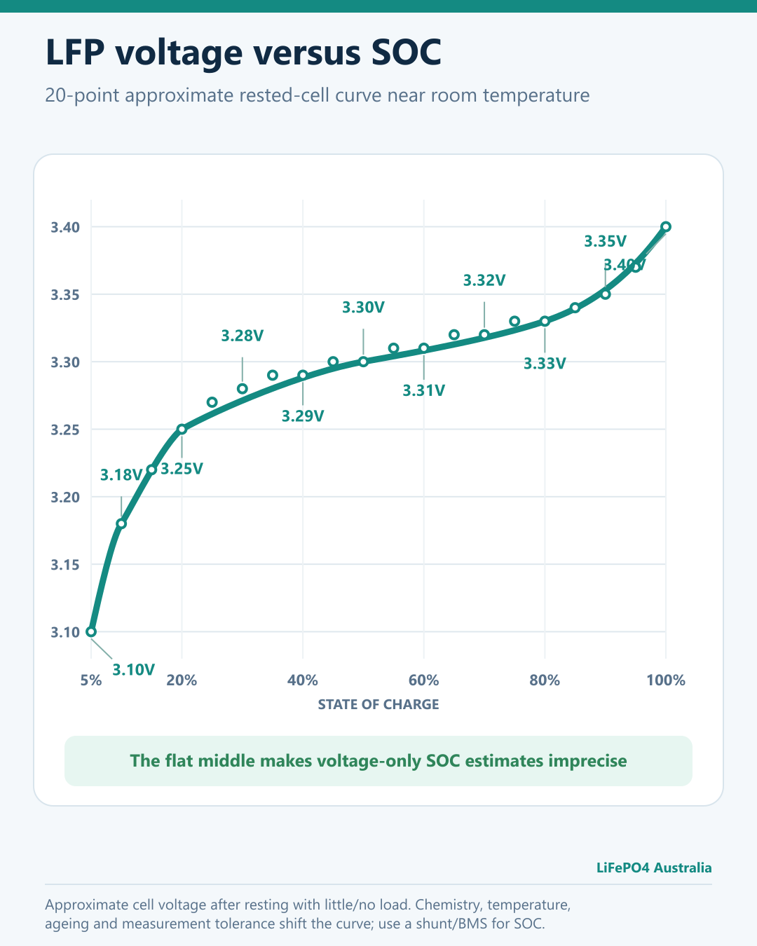
The curve uses twenty approximate orientation points at 5% SOC increments. More point voltages are labelled, with leader lines keeping the text clear of the curve. This remains an approximate rested-voltage guide near room temperature, not a replacement for a calibrated shunt or BMS SOC calculation.
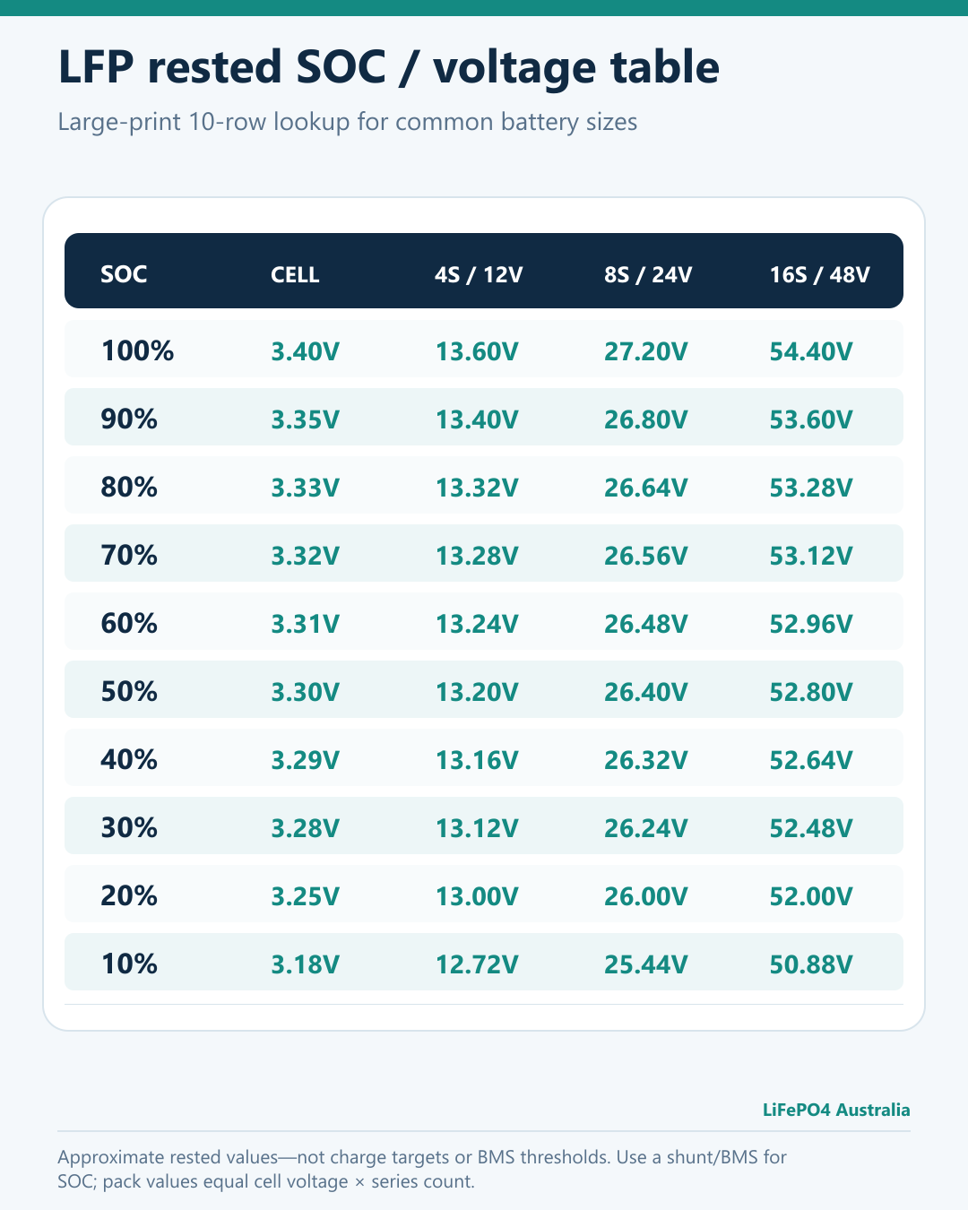
The separate large-print table provides cell, 4S, 8S and 16S values in ten practical rows so it remains easier to read on a phone. These are approximate rested values—not charger targets or BMS protection thresholds.
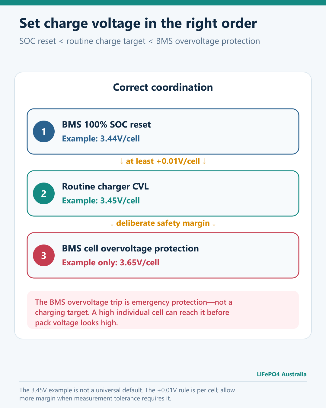
The 0.01V minimum is per cell and may need to be larger once measurement accuracy and system tolerances are considered.
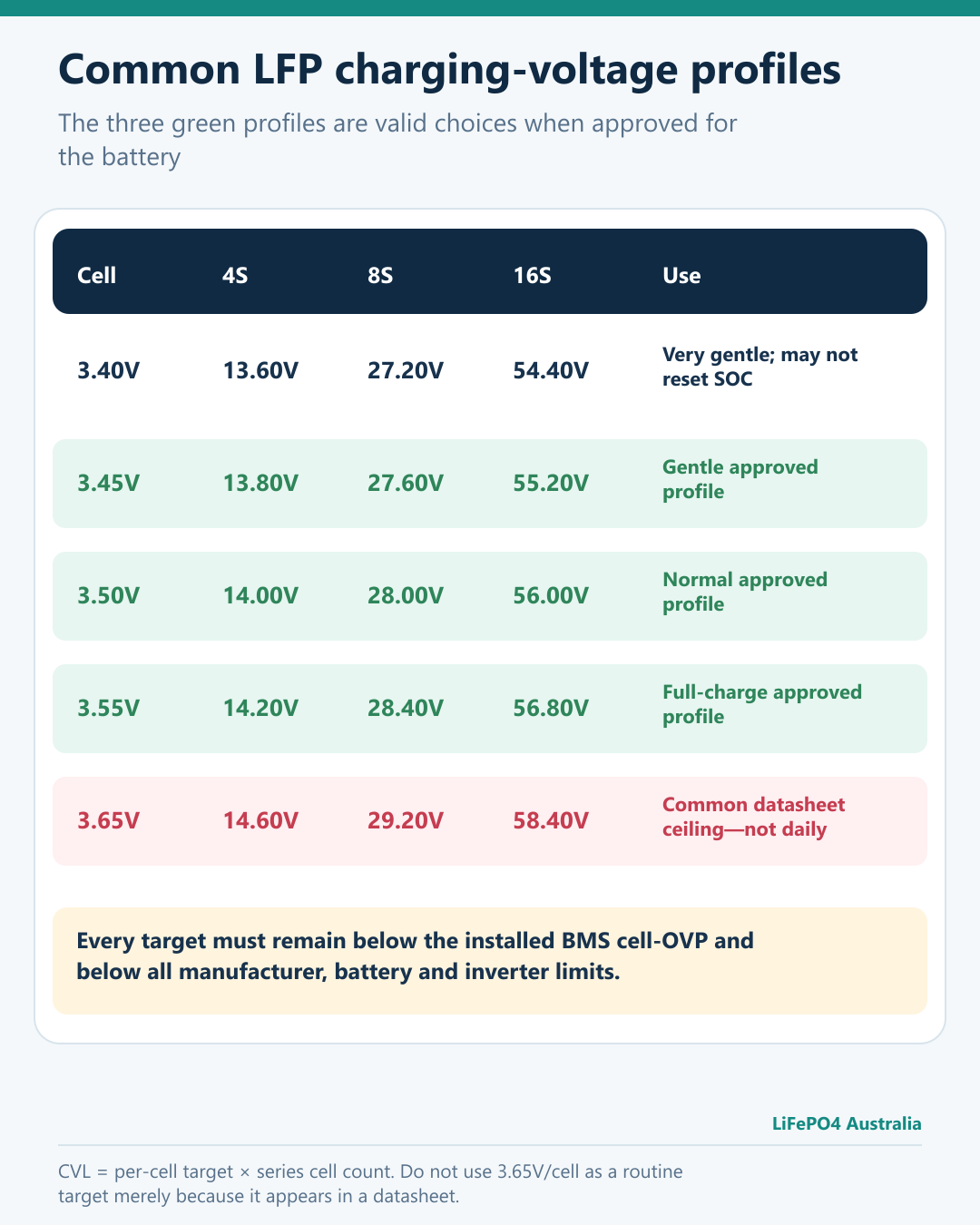
Pack values are exact series multiplication. The three green profiles—3.45V, 3.50V and 3.55V/cell—are all valid choices when approved for the battery; they are not a universal ranking of battery health.
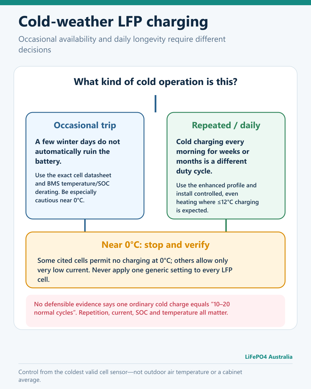
Occasional manufacturer-compliant cold operation is different from daily winter charging. Near 0°C, stop and verify the exact cell limits.
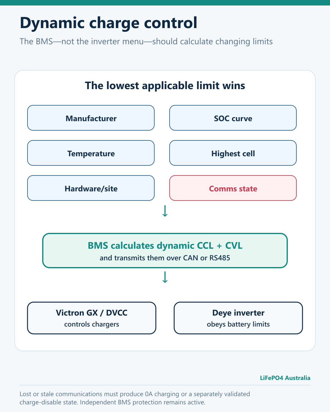
The BMS should calculate CCL and CVL; the compatible inverter and chargers should obey them.
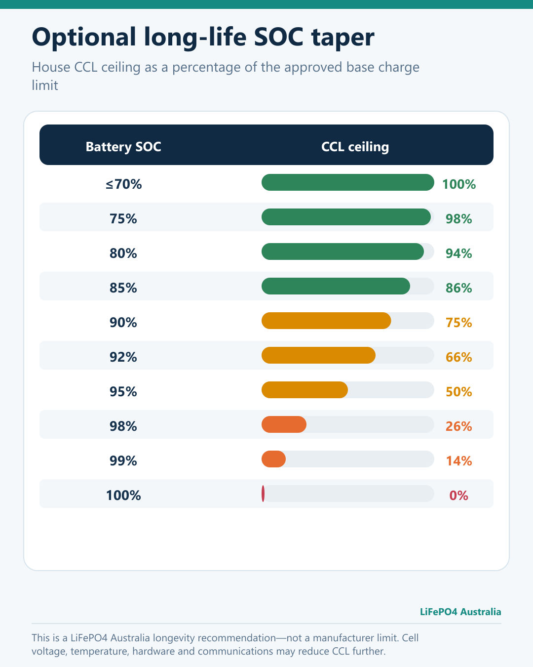
This taper is a LiFePO4 Australia recommendation, not a manufacturer limit.
Before you finish
- Know the exact cell model, specification number and revision in the battery.
- Set the completed battery's approved base charge limit; never assume the cell maximum is the system maximum.
- Use dynamic BMS communications where the charger/inverter supports them.
- Apply the lower of manufacturer, SOC, temperature, voltage, hardware and site limits.
- For repetitive cold-climate service, use the enhanced profile and do not charge when the coldest cell is 12°C or lower.
- For occasional cold-weather use outside that profile, obey the exact manufacturer/BMS derating and treat operation near 0°C with particular caution.
- Install an approved heater where repetitive or daily charging below the enhanced-profile range is expected.
- Confirm that every charging source obeys the BMS, including PV, grid charger, DC-DC charger and alternator.
- Keep operating logs that show cell voltage, temperature, SOC, current, CCL, CVL, faults and communications state.
- Treat 100% SOC and 3.65V/cell as special conditions, not routine daily targets, unless the approved battery procedure says otherwise.
Related LiFePO4 Australia guides
- LiFePO4 SOC and everything else you need to know
- LiFePO4 float voltage
- How to connect a JK inverter BMS to Victron
- Why limiting charge rate can extend LFP battery life
- LiFePO4 cycle life: what the numbers mean
Disclaimers
This guide provides a conservative operational recommendation, not a guarantee of a particular cycle life, calendar life or warranty outcome. Battery ageing depends on temperature, time, average SOC, depth of discharge, current, cell quality, mechanical design, compression, thermal uniformity, balancing, voltage control, system integration and operating history.
The manufacturer figures are tied to the document revisions listed below. A newer supplier-controlled specification or a specification supplied with your battery may contain different limits; where it does, follow the document approved for that battery.
The completed battery designer and installer remain responsible for correct electrical protection, mechanical restraint, thermal design, fire safety, applicable standards, inverter compatibility, commissioning and ongoing maintenance. If any value in this guide conflicts with the approved specification for the installed battery, the lower and safer approved value applies until the conflict is resolved by qualified engineering review.
Datasheets and technical sources
Each manufacturer figure is tied to a named document, revision and date where available. Key sources include:
- EVE LF105 Version E, PBRI-LF105-D06-01
- EVE LF230 Version C, PBRC-LF230-S01-LF, March 2022
- EVE LF304 Version A, RD-LF304-S01-LF, May 2021
- EVE LF304 Version C, PBRC-LF304-S01-LF, April 2022
- EVE LF304 Version E, PBRI-LF304-D06-01, May 2023
- EVE MB31 Version A, PBRI-MB31-D06-01, November 2023
- CATL 302Ah public specification CTPS-71H3L7-01
- Victron GX DVCC documentation
- Victron Lithium Battery Smart charging recommendations
- Deye current product/manual library
- CATL liquid-cooling and service-life statement
- HiTHIUM official 314Ah product data
- REPT BATTERO energy-storage cell portfolio
- CALB current energy-storage product claims
- Wu et al., low-temperature LiFePO4 charge-rate cycle study
- Zhang et al., 230Ah LFP natural OCV/SOC testing at 25°C
- LiFePO4 OCV/SOC testing across temperature scenarios